Performance Optimization in DSP
The purpose of this lecture is as follows.
To describe the factors that affect performance in DSP software
To analyze the assembly code of typical DSP operations
Attention
The handout sheet for this lecture can be downloaded
The cost of computations in DSP
In this lecture we are interested in understanding the factors that affect the performance of DSP programs. We already know that the processing time per sample cannot exceed the sample period. Within the interval of a single sample period, the processor has to acquire data from the ADC, process the new sample following the rules of the DSP algorithm, and finally convert the output sample to a DAC voltage.
We will break down the processing time of a DSP in its components, and then clarify how these components can be reduced through optimization. In this lecture, the emphasis lies on the software processing, i.e., the C code written for the Cortex-M4 ARM processor.
The Software Flow
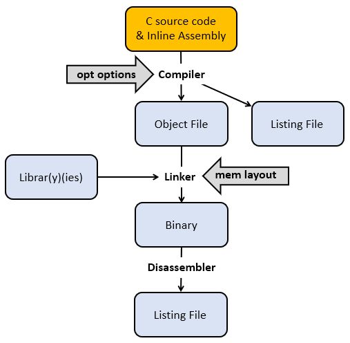
We start by briefly reminding the flow from C source code to a binary program for a DSP processor. A C compiler, which accepts optimization flags, converts C code with optional inline assembly into an object file, which contains processor instructions. The C compiler also produces a listing file which relates C code and processor instructions.
The object file is not yet a binary program. All external symbols (such as library functions) have to be resolved, and every variable and function has to be mapped to a concrete memory address following a specific memory layout. Finally, the binary file can be downloaded to the board, and it can also be disassembled to a listing file. The latter may be useful to inspect the implementation of external library functions.
We will be investigating the assembly output of a few DSP programs to investigate the factors that influence the complexity and cost of DSP program implementation. A useful document to understand assembly code produced by a compiler (and, in this case, assembly code for the ARM Cortex-M4), is the Procedure Call Standard for the Arm® Architecture. This document describes how a function call is implemented, and how basic data types (in C, C++) are implemented. Of particular interest is Core registers and AAPCS usage Table in this document, which is reproduced below. This table indicates the functionality of the 16 processor registers in the ARM.
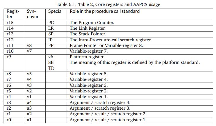
Besides these 16 processor registers, there are an additional 32 registers in the floating-point coprocessor. These registers are addressed as s0-s31 when used as single-precision registers, d0-d15 when used as double-precision registers. d0 overlaps s0-s1, d1 overlaps s2-s3, and so forth. Furthermore when SIMD vector instructions are present, q0-q7 represent quad-word registers.
Examing the basic FIR
Let’s consider the following function, which represents a basic FIR.
uint16_t processSample(uint16_t x) {
    float32_t input = xlaudio_adc14_to_f32(x);

    taps[0] = input;

    float32_t q = 0.0;
    uint16_t i;
    for (i = 0; i<NUMTAPS; i++)
        q += taps[i] * B[i];

    for (i = NUMTAPS-1; i>0; i--)
        taps[i] = taps[i-1];

    return xlaudio_f32_to_dac14(q);
}
Note
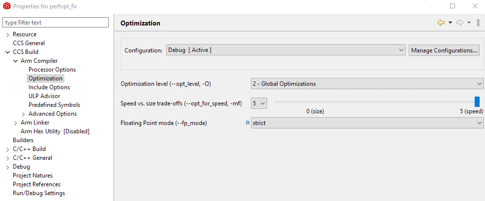
To set the optimization level of the compiler, right-click a project and select CCS Build - ARM Compiler - Optimization.
To inspect the assembly listing produced by the compiler, open the Debug folder in the project and look for the listing (.lst) file. You will find that listing files are very verbose; the code shown further is an edited version with the majority of comments removed.
We start by examining the output of the compiler without any optimization. Such code is sub-optimal, but also very easy to understand.
processSample:
        PUSH      {A2, A3, A4, LR}

;   float32_t input = xlaudio_adc14_to_f32(x);

        STRH      A1, [SP, #8]
        LDRH      A1, [SP, #8]
        BL        xlaudio_adc14_to_f32
        VSTR.32   S0, [SP, #0]

;    taps[0] = input;

        LDR       A2, $C$CON7
        LDR       A1, [SP, #0]
        STR       A1, [A2, #0]

;    float32_t q = 0.0;

        LDR       A1, $C$FL1
        STR       A1, [SP, #4]

;    for (i = 0; i<NUMTAPS; i++)

        MOVS      A1, #0
        STRH      A1, [SP, #10]

        LDRH      A1, [SP, #10]
        CMP       A1, #8
        BGE       ||$C$L61||


;        q += taps[i] * B[i];

        LDRH      A4, [SP, #10]
        LDR       A1, $C$CON7
        LDRH      A3, [SP, #10]
        LDR       A2, $C$CON8
        VLDR.32   S1, [SP, #4]
        ADD       A1, A1, A4, LSL #2
        VLDR.32   S0, [A1, #0]
        ADD       A2, A2, A3, LSL #2
        VLDR.32   S2, [A2, #0]
        VMLA.F32  S1, S2, S0
        VSTR.32   S1, [SP, #4]

        LDRH      A1, [SP, #10]
        ADDS      A1, A1, #1
        STRH      A1, [SP, #10]

        LDRH      A1, [SP, #10]
        CMP       A1, #8
        BLT       ||$C$L60||
        ; BRANCHCC OCCURS {||$C$L60||}

||$C$L61||:

;    for (i = NUMTAPS-1; i>0; i--)

        MOVS      A1, #7
        STRH      A1, [SP, #10]

        LDRH      A1, [SP, #10]
        CMP       A1, #0
        BLE       ||$C$L63||

||$C$L62||:

;       taps[i] = taps[i-1];

        LDRH      A1, [SP, #10]
        LDR       A2, $C$CON7
        LDRH      A3, [SP, #10]
        LDR       A4, $C$CON7
        LSLS      A1, A1, #2
        SUBS      A1, A1, #4
        LDR       A1, [A2, +A1]
        STR       A1, [A4, +A3, LSL #2]

        LDRH      A1, [SP, #10]
        SUBS      A1, A1, #1
        STRH      A1, [SP, #10]

        LDRH      A1, [SP, #10]
        CMP       A1, #0
        BGT       ||$C$L62||

; return xlaudio_f32_to_dac14(q);

||$C$L63||:

        VLDR.32   S0, [SP, #4]
        BL        xlaudio_f32_to_dac14

        POP       {A2, A3, A4, PC}
The instructions fall apart in three broad categories.
Some instructions are related to the implementation of control flow operations in C. Loop counters, for example, imply the creation of a loop counter variable, a loop counter increment operations, and one or more conditional jump instructions.
Some instructions are related to the storage and retrieval of variables. In particular, variables are either stored in the stack (local variables such as
inputandq), or else in main memory (global variables such astapsandC).Some instructions do actual computations, and for a FIR filter these computations consist of multiply and accumulate.
Let’s examine each of these instruction types in further detail.
Control Flow
The ARM Cortex-M4 is a pipelined processor, meaning that pipeline hazards can occur due to branches (control hazard) or memory access (data hazard). The ARM Cortex-M4 has a 3-stage pipeline with branch speculation, which reduces some of the penalty of a control hazard.
However, when considering a C program, it is useful to evaluate all aspects of the control flow implementation of the C program. For example, let us highlight all instructions related to the loop counter.
||$C$L61||:

;    for (i = NUMTAPS-1; i>0; i--)

        MOVS      A1, #7
        STRH      A1, [SP, #10]

        LDRH      A1, [SP, #10]
        CMP       A1, #0
        BLE       ||$C$L63||

||$C$L62||:

        ...

        LDRH      A1, [SP, #10]
        SUBS      A1, A1, #1
        STRH      A1, [SP, #10]

        LDRH      A1, [SP, #10]
        CMP       A1, #0
        BGT       ||$C$L62||

||$C$L63||:
There is, of course, overhead because of the absence of optimization. The loop counter is moved on and off the stack multiple times. On the other hand, one can see that a simple loop iteration without optimization costs 6 instructions per loop iteration, where most of the memory-load instructions will cause a data-hazard, and where one of the instructions is a branch. Clearly, loop counters in DSP programs are not free, and for this reason, short loops with known bounds are unrolled.
Data Movement
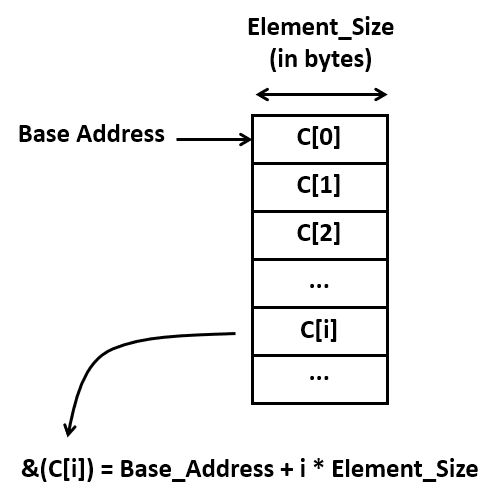
A second important source of code is the computation of addresses. Each indexed element access requires the computation of the address where that element is stored. This address is given by the base address plus the size of an element (in bytes) times the index.
Address calculations quickly become an important factor in additional ‘hidden’ computation costs. Consider for example the assembly code required for a simple array-to-array copy. It contains 10 instructions! Again, there are some obvious inefficiencies in this code, but even without those, it’s clear that there will be multiple instructions involved for every memory-to-memory copy.
;       taps[i] = taps[i-1];

        LDRH      A1, [SP, #10]            ; A1 = i
        LDR       A2, $C$CON7              ; A2 = taps
        LDRH      A3, [SP, #10]            ; A3 = i
        LDR       A4, $C$CON7              ; A4 = taps
        LSLS      A1, A1, #2               ; A1 = i * 4
        SUBS      A1, A1, #4               ; A1 = (i -1) * 4
        LDR       A1, [A2, +A1]            ; A1 = MEM[taps + (i-1) * 4]
        STR       A1, [A4, +A3, LSL #2]    ; MEM[taps + i * 4] = A1
Calculations
Finally, there are the actual computations, which include the multiply-accumulate operations of the FIR. The ARM processor has a relatively powerful execution unit, which can combine shifting and adding in a single operation. Consider for example the expression q += taps[i] * B[i];
Stripping out the overhead of the address computations for taps[i] and B[i],
we are left with the following compact sequence.
;        q += taps[i] * B[i];

        VLDR.32   S1, [SP, #4]          S1 = q
        VLDR.32   S0, [A1, #0]          S0 = taps[i]
        VLDR.32   S2, [A2, #0]          S2 = B[i]
        VMLA.F32  S1, S2, S0            S1 = q + S0 * S2
        VSTR.32   S1, [SP, #4]          store q
In summary, the bulk of the instructions performed by the program are not directly related to the FIR multiply-accumulate operations. Instead, the bulk of instructions are related to various management tasks in C: supporting control flow operations, and supporting data structures in memory, for example. It is impossible to do good DSP program optimization while ignoring this aspect.
Optimizing for Size
When you write C code, the most important source of optimization is the C compiler. For simple programs (including the FIR design that we are currently investigating), the C compiler is very effective at analyzing the properties of the code and transforming it for minimal footprint or maximal performance.
When optimizing for minimal footprint, we value code size over processor clock cycles. In an embedded processor, optimizing for size is important to minimize storage needs.
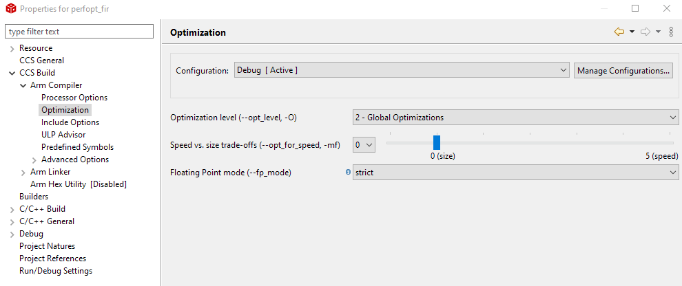
Let’s consider the impact of compiler optimization, set of Global Optimizations while minimizing code size. The FIR program considered earlier now shrinks to the following set of instructions.
processSample:
        PUSH      {V4, LR}
        BL        xlaudio_adc14_to_f32
        MOVS      V4, #8         ; 8 iterations
        LDR       A2, $C$CON1    ; load base address taps
        LDR       A1, $C$FL1     ; load constant 0.0
        LDR       A3, $C$CON2    ; load base address B

        VSTR.32   S0, [A2, #0]   ; taps[0] = input
        MOV       A4, A2         ; A4 = case address taps

        VMOV      S0, A1         ; clear accumulator S0
||$C$L1||:
        LDR       A1, [A4], #4   ; A1 = tap[1]; postinc A4
        VMOV      S1, A1         ; S1 = S1
        LDR       A1, [A3], #4   ; A1 = B[1]; postinc A3
        VMOV      S2, A1         ; S2 = A1
        SUBS      V4, V4, #1     ; iterations--
        VMLA.F32  S0, S2, S1     ; S0 = S0 + S1 * S2
        BNE       ||$C$L1||

        ADDS      A2, A2, #28    ; A2 = taps + (NUMTAPS-1)*4
        MOVS      A1, #7         ; 7 iterations
||$C$L2||:
        VLDR.32   S1, [A2, #-4]  ; S1 = taps[i-1];
        VMOV      A3, S1         ; A3 = S1
        SUBS      A1, A1, #1     ; decrement loopcounter
        STR       A3, [A2], #-4  ; taps[i] = S1; postdec A2
        BNE       ||$C$L2||

        BL        xlaudio_f32_to_dac14
        POP       {V4, PC}
This code is worth discussing further, as it testifies the capabilities of compiler optimization.
The amount of data movement is drastically reduced. In the non-optimized version, every local variable is stored on the stack. For every access, the local variable is read into a processor register. When the variable is modified, it is written back onto the stack.
The code has been converted to use pointer arithmetic rather than using address expressions. Consider the a loop with
B[i]andtaps[i]:for (i = 0; i<NUMTAPS; i++) q += taps[i] * B[i];
After compiler optimization, two pointers are introduced as follows:
ptr1 = taps;
ptr2 = B;
for (i = 0; i<NUMTAPS; i++)
    q += (*ptr1++ * *ptr2++);
Note that instructions can support a ‘postincrement’ or ‘postdecrement’ addressing mode. That means that the register used to compute an address can be modified as a result of the instruction. For example, the following instruction has two effects: it loads A1 with the contents of the memory location addressed by A3, and it also modifies A3 by adding the value 4 after memory address is used.
LDR A1, [A3], #4 ; A1 = B[1]; postinc A3
The loop counts down, instead of up. When decrementing a loop counter to zero, a simple test on the zero flag of the processor is sufficient to detect the end of the loop. When a loop counter counts up, an additional compare instruction is needed.
Optimizing for Performance
The compiler can also optimize for performance. In that case the generated code is dramatically different from the optimization for size.
In this case, the compiler completely unrolls the loop, removing every control operation, including loop counter management and branch instructions. The resulting code contains only memory-load and -store, as well as arithmetic.
processSample:
        PUSH      {A4, LR}
        BL        xlaudio_adc14_to_f32
        MOVS      A1, #0
        MOVW      A2, B+0
        VMOV.F32  S1, S0
        MOVT      A1, #0
        VMOV      S0, A1
        MOVT      A2, B+0
        VLDR.32   S2, [A2, #0]
        VMLA.F32  S0, S1, S2            ; S0 = S0 + B[0] * input
        MOVW      A1, taps+0            ; A1 = base address taps
        MOVT      A1, taps+0
        VLDR.32   S7, [A1, #4]
        VLDR.32   S2, [A2, #4]
        VMLA.F32  S0, S7, S2            ; S0 = S0 + B[1] * taps[1]
        VLDR.32   S6, [A1, #8]
        VLDR.32   S2, [A2, #8]
        VMLA.F32  S0, S6, S2            ; S0 = S0 + B[2] * taps[2]
        VLDR.32   S5, [A1, #12]
        VLDR.32   S2, [A2, #12]
        VMLA.F32  S0, S5, S2            ; S0 = S0 + B[3] * taps[3]
        VLDR.32   S4, [A1, #16]
        VLDR.32   S2, [A2, #16]
        VMLA.F32  S0, S4, S2            ; S0 = S0 + B[4] * taps[4]
        VLDR.32   S3, [A1, #20]
        VLDR.32   S2, [A2, #20]
        VMLA.F32  S0, S3, S2            ; S0 = S0 + B[5] * taps[5]
        VLDR.32   S8, [A2, #24]
        VLDR.32   S2, [A1, #24]
        VMLA.F32  S0, S2, S8            ; S0 = S0 + B[6] * taps[6]
        VLDR.32   S9, [A2, #28]
        VLDR.32   S8, [A1, #28]
        VMLA.F32  S0, S9, S8            ; S0 = S0 + B[7] * taps[7]
        VSTR.32   S1, [A1, #0]          ;
        VSTR.32   S1, [A1, #4]          ; shift taps
        VSTR.32   S4, [A1, #20]         ;   using
        VSTR.32   S5, [A1, #16]         ;     back
        VSTR.32   S6, [A1, #12]         ;       copies
        VSTR.32   S7, [A1, #8]          ;         in S1 .. S7
        VSTR.32   S3, [A1, #24]         ;
        VSTR.32   S2, [A1, #28]         ;
        BL        xlaudio_f32_to_dac14
        POP       {A4, PC}
Comparing Non-optimized and Optimized Code
Let’s compare the three examples we discussed so far: the unoptimized code, versus the compiler-optimized code (optimized for size), versus performance-optimized code (optimized for performance). For each implementation, we collect the following metrics.
The number of instructions in the static program image. This metric represents the cost of storing instructions.
The number of instructions executed to deal with data movement, including address expressions, and load/store operations.
The number of instructions executed to deal with control, including loop counting and branches.
The number of instructions executed for actual FIR calculations, such as multiply and accumulate.
The cycle count of the
processSamplefunction.
The number of instructions in the static program image can directly counted from the assembly listing. To derive the numbers for 2, 3, 4 the following table, we construct a table that reflects the number of times each instruction is executed, along with the category of each instruction. Next, we accumulate the instruction count for each category.
Non-optimized Code
processSample: |
Executes |
Data Move |
Control |
Compute |
PUSH {A2, A3, A4, LR} |
1 |
x |
||
STRH A1, [SP, #8] |
1 |
x |
||
LDRH A1, [SP, #8] |
1 |
x |
||
BL xlaudio_adc14_to_f32 |
1 |
x |
||
VSTR.32 S0, [SP, #0] |
1 |
x |
||
LDR A2, $C$CON7 |
1 |
x |
||
LDR A1, [SP, #0] |
1 |
x |
||
STR A1, [A2, #0] |
1 |
x |
||
LDR A1, $C$FL1 |
1 |
x |
||
STR A1, [SP, #4] |
1 |
x |
||
MOVS A1, #0 |
1 |
x |
||
STRH A1, [SP, #10] |
1 |
x |
||
LDRH A1, [SP, #10] |
1 |
x |
||
CMP A1, #8 |
1 |
x |
||
BGE ||$C$L61|| |
1 |
x |
||
||$C$L60||: LDRH A4, [SP, #10] |
8 |
x |
||
LDR A1, $C$CON7 |
8 |
x |
||
LDRH A3, [SP, #10] |
8 |
x |
||
LDR A2, $C$CON8 |
8 |
x |
||
VLDR.32 S1, [SP, #4] |
8 |
x |
||
ADD A1, A1, A4, LSL #2 |
8 |
x |
||
VLDR.32 S0, [A1, #0] |
8 |
x |
||
ADD A2, A2, A3, LSL #2 |
8 |
x |
||
VLDR.32 S2, [A2, #0] |
8 |
x |
||
VMLA.F32 S1, S2, S0 |
8 |
x |
||
VSTR.32 S1, [SP, #4] |
8 |
x |
||
LDRH A1, [SP, #10] |
8 |
x |
||
ADDS A1, A1, #1 |
8 |
x |
||
STRH A1, [SP, #10] |
8 |
x |
||
LDRH A1, [SP, #10] |
8 |
x |
||
CMP A1, #8 |
8 |
x |
||
BLT ||$C$L60|| |
8 |
x |
||
||$C$L61||: MOVS A1, #7 |
1 |
x |
||
STRH A1, [SP, #10] |
1 |
x |
||
LDRH A1, [SP, #10] |
1 |
x |
||
CMP A1, #0 |
1 |
x |
||
BLE ||$C$L63|| |
1 |
x |
||
||$C$L62||: LDRH A1, [SP, #10] |
7 |
x |
||
LDR A2, $C$CON7 |
7 |
x |
||
LDRH A3, [SP, #10] |
7 |
x |
||
LDR A4, $C$CON7 |
7 |
x |
||
LSLS A1, A1, #2 |
7 |
x |
||
SUBS A1, A1, #4 |
7 |
x |
||
LDR A1, [A2, +A1] |
7 |
x |
||
STR A1, [A4, +A3, LSL #2] |
7 |
x |
||
LDRH A1, [SP, #10] |
7 |
x |
||
SUBS A1, A1, #1 |
7 |
x |
||
STRH A1, [SP, #10] |
7 |
x |
||
LDRH A1, [SP, #10] |
7 |
x |
||
CMP A1, #0 |
7 |
x |
||
BGT ||$C$L62|| |
7 |
x |
||
||$C$L63||: VLDR.32 S0, [SP, #4] |
1 |
x |
||
BL xlaudio_f32_to_dac14 |
1 |
x |
||
POP {A2, A3, A4, PC} |
1 |
x |
Size-optimized Code
processSample: |
Executes |
Data Move |
Control |
Compute |
PUSH {V4, LR} |
1 |
x |
||
BL xlaudio_adc14_to_f32 |
1 |
x |
||
MOVS V4, #8 |
1 |
x |
||
LDR A2, $C$CON1 |
1 |
x |
||
LDR A1, $C$FL1 |
1 |
x |
||
LDR A3, $C$CON2 |
1 |
x |
||
VSTR.32 S0, [A2, #0] |
1 |
x |
||
MOV A4, A2 |
1 |
x |
||
VMOV S0, A1 |
1 |
x |
||
||$C$L1||: LDR A1, [A4], #4 |
8 |
x |
||
VMOV S1, A1 |
8 |
x |
||
LDR A1, [A3], #4 |
8 |
x |
||
VMOV S2, A1 |
8 |
x |
||
SUBS V4, V4, #1 |
8 |
x |
||
VMLA.F32 S0, S2, S1 |
8 |
x |
||
BNE ||$C$L1|| |
8 |
x |
||
ADDS A2, A2, #28 |
1 |
x |
||
MOVS A1, #7 |
1 |
x |
||
||$C$L2||: VLDR.32 S1, [A2, #-4] |
7 |
x |
||
VMOV A3, S1 |
7 |
x |
||
SUBS A1, A1, #1 |
7 |
x |
||
STR A3, [A2], #-4 |
7 |
x |
||
BNE ||$C$L2|| |
7 |
x |
||
BL xlaudio_f32_to_dac14 |
1 |
x |
||
POP {V4, PC} |
1 |
x |
Performance-optimized Code
processSample: |
Executes |
Data Move |
Control |
Compute |
PUSH {A4, LR} |
1 |
x |
||
BL xlaudio_adc14_to_f32 |
1 |
x |
||
MOVS A1, #0 |
1 |
x |
||
MOVW A2, B+0 |
1 |
x |
||
VMOV.F32 S1, S0 |
1 |
x |
||
MOVT A1, #0 |
1 |
x |
||
VMOV S0, A1 |
1 |
x |
||
MOVT A2, B+0 |
1 |
x |
||
VLDR.32 S2, [A2, #0] |
1 |
x |
||
VMLA.F32 S0, S1, S2 |
1 |
x |
||
MOVW A1, taps+0 |
1 |
x |
||
MOVT A1, taps+0 |
1 |
x |
||
VLDR.32 S7, [A1, #4] |
1 |
x |
||
VLDR.32 S2, [A2, #4] |
1 |
x |
||
VMLA.F32 S0, S7, S2 |
1 |
x |
||
VLDR.32 S6, [A1, #8] |
1 |
x |
||
VLDR.32 S2, [A2, #8] |
1 |
x |
||
VMLA.F32 S0, S6, S2 |
1 |
x |
||
VLDR.32 S5, [A1, #12] |
1 |
x |
||
VLDR.32 S2, [A2, #12] |
1 |
x |
||
VMLA.F32 S0, S5, S2 |
1 |
x |
||
VLDR.32 S4, [A1, #16] |
1 |
x |
||
VLDR.32 S2, [A2, #16] |
1 |
x |
||
VMLA.F32 S0, S4, S2 |
1 |
x |
||
VLDR.32 S3, [A1, #20] |
1 |
x |
||
VLDR.32 S2, [A2, #20] |
1 |
x |
||
VMLA.F32 S0, S3, S2 |
1 |
x |
||
VLDR.32 S8, [A2, #24] |
1 |
x |
||
VLDR.32 S2, [A1, #24] |
1 |
x |
||
VMLA.F32 S0, S2, S8 |
1 |
x |
||
VLDR.32 S9, [A2, #28] |
1 |
x |
||
VLDR.32 S8, [A1, #28] |
1 |
x |
||
VMLA.F32 S0, S9, S8 |
1 |
x |
||
VSTR.32 S1, [A1, #0] |
1 |
x |
||
VSTR.32 S1, [A1, #4] |
1 |
x |
||
VSTR.32 S4, [A1, #20] |
1 |
x |
||
VSTR.32 S5, [A1, #16] |
1 |
x |
||
VSTR.32 S6, [A1, #12] |
1 |
x |
||
VSTR.32 S7, [A1, #8] |
1 |
x |
||
VSTR.32 S3, [A1, #24] |
1 |
x |
||
VSTR.32 S2, [A1, #28] |
1 |
x |
||
BL xlaudio_f32_to_dac14 |
1 |
x |
||
POP {A4, PC} |
1 |
x |
Summary Table
ProcessSample |
Non-optimized |
Optimized (size) |
Optimized (Performance) |
|---|---|---|---|
Instructions in Binary |
54 |
25 |
43 |
Exec Ins Data Movement |
147 |
62 |
33 |
Exec Ins Control |
102 |
34 |
2 |
Exec Ins Calculations |
8 |
8 |
8 |
Cycle Count |
533 |
188 |
110 |
We make the following observations. First, performance can be dramatically improved through compiler optimization. We observe a factor 4.84x using automatic techniques (this could be even further improved with manual optimizations such as the circular-buffer optimization we discussed earlier).
Second, the number of instructions devoted to calculations remains constant. This is not a surprise, since we have to compute all taps of the filter. The only method to reduce the calculations further would be to exploit the knowledge of the filter coefficient values, for example skipping the multiplications with zero, or using add-shift expansion on constant multiplications.
Conclusions
We identified three factors that determine the execution time of DSP algorithm: the computations such as multiply and accumulate, the control operations such as loops, and the data load and store operations with address calculations.
The overhead of control operations and data load and store operations is significant, but it can be greatly reduced with compiler optimization. The compiler optimizer makes a trade-off between optimizing for storage cost (code size), and optimizing for performance. Each of these have a different impact on the balance of computation/control/data load-store operations.