Lab 5x: Real-Time Pitch Shifting
This lab was created by Robbie Oleynick (rpoleynick@wpi.edu)
The purpose of this lab is as follows:
To implement a basic pitch-shifting guitar pedal
To investigate the effects of pitch shifting in the frequency domain
The Pitch Pedal
This lab will guide you though the implementation of a simple, time-based pitch shifter pedal that could be used in a live performance setting to shift the pitch of an audio signal without speeding or slowing the overall signal.
The Pitch Pedal will consist of five modes denoted by different colors of the RGB LED. Users can switch between modes by pressing the left and right buttons on the LaunchPad. The state logic and RGB LED display code are provided, so you will only be responsible for the signal processing. Successful completion of the lab will involve five operation modes with the following functions:
Mode (LED Color) |
Description |
Pitch Alteration |
|---|---|---|
Red |
Octave up (with crossfade) |
x2 |
Yellow |
Octave up (without crossfade) |
x2 |
Green |
Unaltered pitch |
x1 |
Cyan |
Fourth down |
x0.75 |
Blue |
Octave down (1/2) |
x0.5 |
Operating Principle
A basic method of real-time pitch shifting is using a circular buffer of N previous
readings, and moving the read at a different rate than the write head. This creates an
issue: if the read pointer passes the write pointer, there will be an audible click due
to the change from the least recent to the most recent reading. The solution is
crossfading across the circular buffer to “avoid” the write head.
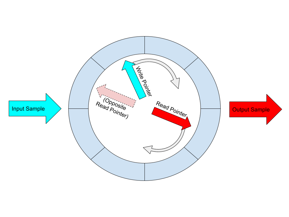
The pitch-shifting algoritm works as follows:
Samples are written into the circular buffer at the write pointer
The read pointer is moved by some amount depending on the pitch shift
Samples are read from the circular buffer at the read pointer, and opposite the read pointer
The two readings are crossfaded depending on how close the read pointer is to the write pointer
The crossfaded value is output
The write pointer is incremented by 1 index
Step 2 will have you implement the pitch-shifting without crossfading, and Step 3 will have you implement the crossfading algorithm.
Step 1: Green Mode (No Pitch Shift)
To begin the lab, accept the lab assignment and download the assignment in
CCS. The main.c file contains a code section marked by BEGIN GIVEN LAB CODE
and END GIVEN LAB CODE. You should not modify the code in this section.
Instead, you will implement the processSample() function and modify the
main() loop to implement the project. Run the starter code and test the provided functionality with the following
steps:
Turn the volume knob to its lowest position and run the starter code
Plug in the headphones and put on the earbuds
Slowly turn the knob up while speaking into the inline microphone
Verify that you can hear your voice through the earbuds
Press the left user button to switch modes (green, cyan, blue, blue, …)
Press the right user button to switch modes (blue, cyan, green, yellow, red, red, …)
Attention
If the inline microphone on the earbuds is not working, you may need to unplug the earbuds and plug them in while the LaunchPad is powered on.
Implementing the Sample Buffer
The pitch shifting algorithm relies on a sample buffer that contains a number of recent samples. Start with a buffer size of 1024 samples. Add the following line of code to your project:
92//////////////////////////////////////////////////////
93//                END GIVEN LAB CODE                //
94// Modify the code below to implement your solution //
95//  v  v  v  v  v  v  v  v  v  v  v  v  v  v  v  v  //
96
97#define BUFSIZE 1024
98
99q15_t buffer[BUFSIZE];
As a reminder, all changes to the code should be below the comment block shown
above. Now, modify the processSample() function to have a writing index
variable and a reading index variable. These indicies should always be in
the range of 0 to BUFSIZE, and each should increment by 1 on every call of
processSample(), looping back to 0 as needed. Set the initial values of the
indicies to be as far from eachother as possible (one should initially be 0 and
the other should initially be BUFSIZE/2).
Now, write the sample x from processSample(uint16_t x) into buffer[]
at the write index and return the sample in buffer[] at the read index.
If the indicies are incrementing and looping correctly, the audio should sound
rougly identical to the starter code.
Important
Question 1: Generate a 100 Hz sine wave on the Analog Discovery 2 and feed
the signal into J1.2. Swap the XLAUDIO_MIC_IN parameter for
XLAUDIO_J1_2_IN in the main() function to process the signal at pin 2
of header J1. Generate a plot of the input and output signals and explain
why the output signal is delayed from the input signal. What parameters could
be adjusted to decrease the observed latency?
Step 2: Yellow Mode (Octave Up)
Implementing the octave up shift should be very simple if Step 1 is implemented
correctly. Modify the processSample code from step 1 to implement the following
pseudocode:
if glbAudioState is NORMAL
   increase read index by 1
else if glbAudioState is FAST1 or FAST2
   increase read index by 2
Test the Yellow Mode, ensuring that samples are taken from the inline microphone
using the XLAUDIO_MIC_IN parameter. When you sing a tone into the microphone,
you should faintly hear the shifted signal behind a significan amount of noise.
Attention
It may be difficult to hear the altered signal if you are producing the sound yourself. Consider having a partner sing a tone into the microphone, or use a smartphone to feed a song into the inline microphone. The output will constain noise artifacts for Step 2. Step 3 will have you implement the crossfading to reduce the noise.
Important
Question 2: Generate a 445 Hz sine wave on the Analog Discovery 2 and feed
the signal into J1.2. Swap the XLAUDIO_MIC_IN parameter for
XLAUDIO_J1_2_IN in the main() function to process the signal at pin 2
of header J1. Generate a time and frequency plots of the input and output
signals. Explain the expected effect on the frequency of a signal when the read
index is incremented by 2 instead of 1.
Then comment on the noise in the signal. Try adjusting the generated frequency in small amounts and observe that the noise may be louder or quieter for certain values. What is the cause of this clicking noise?
Step 3: Red Mode (Octave Up, Crossfade)
The Yellow Mode does not provide a clean pitch shift of the signal, but the algorithm consists of an optimization that will solve the problem. Instead of only reading from the read index, the output will now consist of a crossfade between the read index, and the index opposite the read buffer. Implement the following pseudocode:
if glbAudioState is FAST1 // yellow mode
   return buffer[readIndex]
else
   s0 = f0 * buffer[readIndex]
   s1 = f1 * buffer[(readIndex + BUFSIZE/2) % BUFSIZE]
   return s0 + s1

// f0 is a fractional value between 0 and 1
//   0 represents the positions of the read index and the write index lining up exactly
//   1 represents the positions of the indicies being separated by BUFSIZE / 2
// f1 is a fractional value between 0 and 1 that is (1 - f0)
This pseudocode “avoids” the write index by smoothly transitioning across the
circular buffer. Your job is to determine f0 and f1 using the values of
the read and write indicies. You may choose to optimize the implementation to avoid
floating point arithmetic by using bit shifting and integer multiplication, or
adjust the sample rate if the processSample() call takes too long.
Important
Question 3: Repeat the process in Question 2 and generate new plots. Comment on the improved quality of the signal. Are there still artifacts in the signal? Use time plots and FFT plots to justify your answer.
Step 4: Cyan Mode (Fourth Down) and Blue Mode (Octave Down)
We will now implement the cyan and blue modes. The blue mode should shift the input signal an octave down. The cyan mode should shift the signal a perfect fourth down (75% speed readuction, or 3/4 the original pitch).
Modify the code to store the read index as a floating point number instead of an integer. The simplest way to do this is to store the floating point as a new variable, and cast the floating point number to an integer and store it in a local variable with the original name of your read index. The following pseudocode shows this approach:
if flbAudioState is SLOW2
   increase read_float by 0.5
else if glbAudioState is SLOW1
   increase read_float by 0.75
else if glbAudioState is NORMAL
   increase read_float by 1.0
else if glbAudioState is FAST1 or FAST2
   increase read_float by 2.0

uint8_t read_index = (uint8_t) read_float
Important
Question 4: Repeat the process in Question 2 and generate new plots. Comment on the quality of the downward pitch shifting.
Bonus: Filtering
The Pitch Pedal could be improved by adding a filter at some point in the signal processing chain. You may consider a filter on the microphone to remove unwanted frequencies from the input. You may consider a filter on the output to remove articfacts from the pitch shifting algorithm.
To earn up to 10 bonus points on this lab, implement a filter that improves the quality of the pitch shift pedal. To earn full bonus points, your report must include:
An oscilloscope output of the original output with observations
An explaination of choice of filter (FIR/IIR, HP/LP/BP/BS)
An oscilloscope output showing the improvement (i.e. reduced noise)
You may:
Use code from previous labs to implement the filter
Change the sample rate to support additional cycles for the filter
Include additional files and add functions below the given code section
Keep in mind that the sample rate affects the filter coefficients, so you must select a sample rate before generating the coefficients in Matlab.
An example of a filter to improve the pitch pedal would be a low-pass filter on the output of the pitch-down modes. Any high-frequency content can be regarded as noise, and may be attenuated to improve clarity. You may also consider filtering the microphone signal prior to writing the value into the buffer.
Important
Bonus: Duplicate the lab5x-pitchpedal folder and name the copy
lab5x-bonusfilter. Implement the filter and include the necessary
report elements as described in this section.
Wrapping Up
The answer to this lab consists of a written report which will be submitted on Canvas by the deadline. Refer to the General Lab Report Guidelines for details on report formatting. You will only submit your written report on Canvas. All code developed must be returned through GitHub.
Follow the principal structure of the report you’ve used for Lab 4 (taking into account any feedback you have received).
Follow the four questions outlined above to structure your report. Use figures, screenshots and code examples where appropriate. Please work out the answers in sufficient detail to show your analysis.
Make sure that you add newly developed projects to github: Use the Team - Share pop-up menu and select your repository for this lab. Further, make sure that you commit and push all changes to the github repository on GitHub classroom. Use the Team - Commit pop-up menu and push all changes.
Be aware that each of the laboratory assignments in ECE4703 will require a significant investment in time and preparation if you expect to have a working system by the assignment’s due date. This course is run in “open lab” mode where it is not expected that you will be able to complete the laboratory in the scheduled official lab time. It is in your best interest to plan ahead so that you can use the TA and instructor’s office hours most efficiently.
Good Luck :)
Grading Rubric
Requirement |
Points |
|---|---|
Question 1 Analysis |
15 |
Question 2 Analysis |
15 |
Question 3 Analysis |
15 |
Question 4 Analysis |
15 |
All projects build without errors or warnings |
5 |
All modes work correctly (3 points per mode) |
15 |
Code is well structured and commented |
5 |
Git Repository is complete and up to date |
5 |
Overall Report Quality (Format, Outline, Grammar) |
10 |
TOTAL |
100 |
Bonus: Filtering is demonstrated and explained |
+ 10 |