DSP Libraries
Contents
The purpose of this lecture is as follows.
To discuss the purpose and use of DSP libraries
To describe the contents of the ARM CMSIS library
To illustrate filter primitives for ARM CMSIS DSP
To describe how DMA I/O is implemented in our DSP applications
To demonstrate the performance gains available from a using DSP library
DSP Libraries: ARM CMSIS
Despite the need for optimize DSP code to achieve real-time performance, there is also a relentless pressure to develop code faster. A solution for this conundrum is to make use of a library with optimized primitives.
The advantage of such a library is threefold. First, a library improves the speed of software development. Second, the library functions can be highly optimized for the underlying architecture. Third, the library’s application programmer’s interface (API) offers a portable design that enables the same application code to execute across multiple platforms.
To support the developer, ARM has published the Common Microcontroller Interface Standard. This is a collection of software functions that aim at supporting the application developer for ARM, regardless of the specific core used. Thus, ARM CMSIS aims at providing a consistent API (Application Programmer’s Interface) for applications that run on the Cortex M-series or A-series.
An important component of the ARM CMSIS linrary is the Digital Signal Processing Lirary. This library provides over 60 DSP functions for various data types: fixed-point (fractional q7, q15, q31) and single precision floating-point (32-bit). Optimized implementations for the SIMD instruction set of Cortex-M4/M7/M33/M35P are included as well.
The ARM CMSIS DSP library is included in the MSP432 SimpleLink software library as source code.
You can find it in source\thirdparty\CMSIS of the SimpleLink Installation
Directory (typically c:\ti\simplelink_msp432p4_sdk_3_40_01_02).
There are a large number of functions included in the library which are documented
in the ARM CMSIS DSP Library.
In this lecture, we will focus on the CMSIS DSP Library support for the DSP functions that we have discussed so far: FIR and IIR filters.
Data Types
The most common data types used by ARM DSP CMSIS are equivalent to the data types that we have used so far.
Type
Precision
Min Value
Max Value
float32_tSingle-precision Floating Point
F32_MAX
F32_MIN
q31_tFixed Point <32,31>
Q31_MAX
Q31_MIN
q15_tFixed Point <16,15>
Q15_MAX
Q15_MIN
In addition, ARM DSP CMSIS makes extensive use of records (structs) to set up
the parameters related to a filter. For example, the following shows the definition
of a data structure used for FIR filtering.
typedef struct {
  uint16_t numTaps;
  q15_t *pState;
  q15_t *pCoeffs;
} arm_fir_instance_q15;
In a arm_fir_instance_q15 record, we will store the number of taps in the filter (numTaps), an array with filter tap values (pState), and an array with filter coefficients (pCoefs). This record is a simple data structure with pointers which does not allocate actual storage. Memory allocation is application dependent, and is therefore left up to the user.
There are similar records for every major function type in ARM DSP CMSIS, and the online documentation can be used to explain each of the fields.
Filtering Operations
All of the filtering functions provided in ARM CMSIS DSP are block-based and work on a block of samples rather than a single sample at a time. For example, a FIR filter function may work on blocks of 8 samples at a time. This means that the ARM CMSIS DSP code for that FIR filter will start from a block of 8 inputs which represents a stream of 8 consecutive inputs samples, and that the FIR filter will create a block of 8 outputs which represents a stream of 8 consecutive output samples.
The following shows a minimal example.
#define BLOCKSIZE 8
#define NUMTAPS 32
int16_t taps[NUMTAPS + BLOCKSIZE - 1];
int coefficients[NUMTAPS] = { ... };
arm_fir_instance_q15 F;

// initialize the FIR
arm_fir_init_q15(F, NUMTAPS, coefficients, taps, BLOCKSIZE);

// execute the FIR
arm_fir_q15(&F, x, y, BUFLEN_SZ);
In this example, a 32-tap FIR is created. The FIR will filter blocks of 8 samples at a time. An array taps of 32 + 8 - 1 taps is required to hold all the data, as well as an array of 32 coefficients. The function arm_fir_init_q15 initializes the FIR data structure.
The function arm_fir_q15 runs the actual filter on a block of x[BLOCKSIZE] samples.
The reason why ARM CMSIS DSP uses block-based processing instead of sample-based processing is rooted in performance considerations. In many cases, a computer architecture becomes more efficient when operations are formulated in bulk. Think for example of the data elements in a cache line which are all read out with a burst memory-read, or of a vector instruction which computes on a vector of data values at a time. Hence, many of the ARM CMSIS DSP library functions are internally optimized to make use of internal computer architecture parallellism.
The consequence of block-based operation, of course, is that one can no longer call a filter one sample at a time. Hence, interrupt driven operation, where samples are produced at an interval of the sample rate period, cannot be used for block-based operation. We can reasonably expect that the processing of N samples may take up to N times the processing of 1 sample.
We will introduce a new real-time input-output primitive to deal with blocks of samples. This new real-time input/output mechanism is called block-based input/output. We will use the term ‘DMA-driven input/output’ to describe this block-based I/O mechanism, mainly because there is a Direct Memory Access peripheral involved.
DMA-driven Input/Output
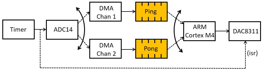
In a block-based processing system, a conversion from sample-rate based processing to block-based, and vice versa, is needed. We make use of a special peripheral called a Direct Memory Access unit. A DMA module performs data movement on behalf of the processor. We can program it with a source address and destination address, and a number of words to copy. When started, the DMA will then automatically copy the block of data. The DMA operation is fairly complex, and in this lecture we will only make a once-over-lightly discussion of it. We will discuss some of the internal details later when we care about detailed performance optimization.
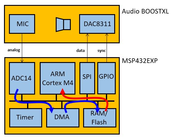
DMA-driven I/O’s idea is to fill up a complete buffer with ADC samples before turing over the buffer to the processor. The processor can then compute on an entire buffer of samples. The following block diagram shows the sequence of operations happening under DMA driven I/O. A periodic timer starts A/D conversions at a specified interval. When an A/D conversion finishes, the DMA module is triggered and the sample is forwarded through a DMA channel to a buffer in main memory. The DMA trigger is a hardware signal; no software is involved to store a sample value in memory. The DMA makes use of a ping and a pong buffer, with the idea that the ARM is only allowed read access to the buffer which is currently not being filled. Thus, when DMA Channel 1 fills the Ping buffer, the ARM reads the Pong buffer, and when DMA Channel 2 fills the Pong buffer, the ARM reads the Ping buffer. The switching between buffers is controlled through a DMA Interrupt Service Routine, and is done behind the scenes. Finally, because the access to the DAC8311 is more complex than the ADC14 (i.e. it requires a combination of GPIO and SPI), no DMA transfers are used to produce output samples.
DMA Example
Here is a complete example of a DMA driven input/output program. The initialization function call includes an additional parameter: the size of the Ping/Pong buffer.
 1#include "xlaudio.h"
 2
 3void processBuffer(uint16_t x[32], uint16_t y[32]) {
 4 uint16_t i;
 5 for (i=0; i<16; i++) {
 6     y[i] = x[i];
 7 }
 8}
 9
10#include <stdio.h>
11
12int main(void) {
13   WDT_A_hold(WDT_A_BASE);
14
15   xlaudio_init_dma(FS_32000_HZ, XLAUDIO_J1_2_IN, BUFLEN_32, processBuffer);
16   xlaudio_run();
17
18   return 1;
19}
FIR Designs using ARM CMSIS DSP
There are several variants of FIR filter implementations in ARM CMSIS DSP. We illustrate a few examples that use single-precision floating point data types. There, of course, variants that use fixed-point precision data types as well. The full list can be found online. We will only discuss the standard block-based FIR.
|
Standard block-based FIR |
|
Decimating block-based FIR |
|
Interpolating block-based FIR |
|
Block-based FIR with sparse coefficients |
|
Lattice block-based FIR |
The following is an example of a FIR with Q15 coefficients.
Important
void arm_fir_q15 ( const arm_fir_instance_q15 *  S,
                   const q15_t *   pSrc,
                   q15_t *   pDst,
                   uint32_t  blockSize
                 )
Parameters
[in]
Spoints to an instance of the Q15 FIR filter structure[in]
pSrcpoints to the block of input data[out]
pDstpoints to the block of output data[in]
blockSizenumber of samples to process
Returns
none
Scaling and Overflow Behavior
The function is implemented using a 64-bit internal accumulator. Both coefficients and state variables are represented in 1.15 format and multiplications yield a 2.30 result. The 2.30 intermediate results are accumulated in a 64-bit accumulator in 34.30 format. There is no risk of internal overflow with this approach and the full precision of intermediate multiplications is preserved. After all additions have been performed, the accumulator is truncated to 34.15 format by discarding low 15 bits. Lastly, the accumulator is saturated to yield a result in 1.15 format.
The following application illustrates the use of arm_fir_q15.
#include "xlaudio.h"

#define BLOCKSIZE 8
#define NUMTAPS 32
q15_t taps[NUMTAPS + BLOCKSIZE - 1];
q15_t coefficients[NUMTAPS] = { (q15_t) (1 * (1 << 15)) };
arm_fir_instance_q15 F;

void processBuffer(uint16_t x[BLOCKSIZE], uint16_t y[BLOCKSIZE]) {
    q15_t xq[BLOCKSIZE], yq[BLOCKSIZE];
    xlaudio_adc14_to_q15_vec(x, xq, BLOCKSIZE);
    arm_fir_q15(&F, xq, yq, BLOCKSIZE);
    xlaudio_q15_to_dac14_vec(yq, y, BLOCKSIZE);
}

#include <stdio.h>

int main(void) {
    WDT_A_hold(WDT_A_BASE);

    arm_fir_init_q15(&F, NUMTAPS, coefficients, taps, BLOCKSIZE);

    xlaudio_init_dma(FS_8000_HZ, XLAUDIO_J1_2_IN, BUFLEN_8, processBuffer);

    uint32_t c = xlaudio_measurePerfBuffer(processBuffer);
    printf("Cycles: %d\n", c);

    xlaudio_run();

    return 1;
}
The
processSampleis now replaced with aprocessBufferfunction, which filters a block of samples. Note that XLAUDIO_LIB has functions to convert a vector of samples from the ADC/to the DAC to internal q15, f32 or q31 datatype.The
mainfunction creates a DMA block-based setup rather than an interrupt-driven sample-based setup. The key parameter isBLOCKSIZE, which describes the blocksize used by the DMA. We will discuss the detailed internal operation of the DMA mechanism in our next lecture. For now, the key point is that the DMA mechanism will collect a block ofBLOCKSIZEsamples (each one sample period apart) from the ADC, and then callsprocessBuffer. After this function returns, the resultingBLOCKSIZEoutput samples are submitted to the DAC, one at a time and spaced one sample period apart.
This function completes in 4999 cycles, which is about 625 cycles per sample. In contrast,
a straightforward FIR filter using an interrrupt-driven I/O routine needs 1556 cycles
per sample. Hence, arm_fir_q15 provides considerable performance improvement.
IIR Designs using ARM CMSIS DSP
Just as with FIR, there are several IIR variants in ARM CMSIS DSP. We illustrate a few examples that use single-precision floating point data types. There, of course, variants that use fixed-point precision data types as well. The full list can be found online. We will discuss Direct Form I Cascade and Direct Form II Transpose Cascade.
|
Direct Form I Cascade block-based IIR |
|
Direct Form II Transpose Casc block-based IIR |
|
IIR Lattice Filter |
The following is an example of a IIR Direct Form I with float32_t coefficients.
Important
void arm_biquad_cascade_df1_f32   (   const arm_biquad_casd_df1_inst_f32 *    S,
                                      const float32_t *   pSrc,
                                      float32_t *     pDst,
                                      uint32_t    blockSize
                                  )
Parameters
[in]
Spoints to an instance of the float32_t biquad cascade structure[in]
pSrcpoints to the block of input data[out]
pDstpoints to the block of output data[in]
blockSizenumber of samples to process
Returns
none
The data structure that holds the coefficients, arm_biquad_casd_df1_inst_f32, is organized in cascade sections as follows (online reference):
typedef struct
{
  uint32_t numStages;
  float32_t *pState;
  const float32_t *pCoeffs;
} arm_biquad_casd_df1_inst_f32;
numStages holds the number of second-order-sections.
pState is an array with state elements, and there are 4 times numStages state elements. The order of state elements is x[n-1], x[n-2], y[n-1], y[n-2].
pCoeffs is an array of 5 times numStages coefficients, each holding the coefficients of a single cascade stage. The order of coefficients are b0, b1, b2, a1, a2, each time repeated per cascade stage.
The following application illustrates the use of arm_biquad_cascade_df1_f32. We assume a filter with two cascade stages, similar to the example discussed in the lecture on IIR design.
#include "xlaudio.h"

#define BLOCKSIZE 8
#define NUMSECTIONS 2
float32_t taps[4 * NUMSECTIONS];
float32_t coefficients[5 * NUMSECTIONS] = {1.0f, 0.0f, 1.0f, -0.707f, 0.25f,
                                           1.0f, 1.0f, 0.0f,  0.707f, 0.25f};
arm_biquad_casd_df1_inst_f32 F;

void processBuffer(uint16_t x[BLOCKSIZE], uint16_t y[BLOCKSIZE]) {
    float32_t xf[BLOCKSIZE], yf[BLOCKSIZE];
    xlaudio_adc14_to_f32_vec(x, xf, BLOCKSIZE);
    arm_biquad_cascade_df1_f32(&F, xf, yf, BLOCKSIZE);
    xlaudio_f32_to_dac14_vec(yf, y, BLOCKSIZE);
}

#include <stdio.h>

int main(void) {
    WDT_A_hold(WDT_A_BASE);

    arm_biquad_cascade_df1_init_f32(&F, NUMSECTIONS, coefficients, taps);
    xlaudio_init_dma(FS_8000_HZ, XLAUDIO_J1_2_IN, BUFLEN_8, processBuffer);

    xlaudio_run();

    return 1;
}