DSP Libraries
The purpose of this lecture is as follows.
To discuss the purpose and use of DSP libraries
To describe the contents of the ARM CMSIS library
To illustrate filter primitives for ARM CMSIS DSP
To demonstrate the performance gains available from a using DSP library
Attention
The examples for this lectures can be downloaded from https://github.com/wpi-ece4703-b24/blockbased
DSP Libraries: ARM CMSIS
Despite the need for optimize DSP code to achieve real-time performance, there is also a relentless pressure to develop code faster. A solution for this conundrum is to make use of a library with optimized primitives.
The advantage of such a library is threefold. First, a library improves the speed of software development. Second, the library functions can be highly optimized for the underlying architecture. Third, the library’s application programmer’s interface (API) offers a portable design that enables the same application code to execute across multiple platforms.
To support the developer, ARM has published the Common Microcontroller Interface Standard. This is a collection of software functions that aim at supporting the application developer for ARM, regardless of the specific core used. Thus, ARM CMSIS aims at providing a consistent API (Application Programmer’s Interface) for applications that run on the Cortex M-series or A-series.
An important component of the ARM CMSIS linrary is the Digital Signal Processing Lirary. This library provides over 60 DSP functions for various data types: fixed-point (fractional q7, q15, q31) and single precision floating-point (32-bit). Optimized implementations for the SIMD instruction set of Cortex-M4/M7/M33/M35P are included as well.
The ARM CMSIS DSP library is included in the MSP432 SimpleLink software library as source code. You can find it in source\thirdparty\CMSIS of the SimpleLink Installation Directory (typically c:\ti\simplelink_msp432p4_sdk_3_40_01_02). There are a large number of functions included in the library which are documented in the ARM CMSIS DSP Library.
In this lecture, we will focus on the CMSIS DSP Library support for the DSP functions that we have discussed so far: FIR and IIR filters.
Data Types
The most common data types used by ARM DSP CMSIS are equivalent to the data types that we have used so far.
Type
Precision
Min Value
Max Value
float32_tSingle-precision Floating Point
F32_MAX
F32_MIN
q31_tFixed Point <32,31>
Q31_MAX
Q31_MIN
q15_tFixed Point <16,15>
Q15_MAX
Q15_MIN
In addition, ARM DSP CMSIS makes extensive use of records (structs) to set up the parameters related to a filter. For example, the following shows the definition of a data structure used for FIR filtering.
typedef struct
{
  uint16_t numTaps;         /**< number of filter coefficients in the filter. */
  q15_t *pState;            /**< points to the state variable array. The array is of length numTaps+blockSize-1. */
  q15_t *pCoeffs;           /**< points to the coefficient array. The array is of length numTaps.*/
} arm_fir_instance_q15;
In a arm_fir_instance_q15 record, we will store the number of taps in the filter (numTaps), an array with filter tap values (pState), and an array with filter coefficients (pCoefs). This record is a simple data structure with pointers which does not allocate actual storage. Memory allocation is application dependent, and is therefore left up to the user.
There are similar records for every major function type in ARM DSP CMSIS, and the online documentation can be used to explain each of the fields.
Filtering Operations
All of the filtering functions provided in ARM CMSIS DSP are block-based and work on a block of samples rather than a single sample at a time. For example, a FIR filter function may work on blocks of 8 samples at a time. This means that the ARM CMSIS DSP code for that FIR filter will start from a block of 8 inputs which represents a stream of 8 consecutive inputs samples, and that the FIR filter will create a block of 8 outputs which represents a stream of 8 consecutive output samples.
The following shows a minimal example.
#define BLOCKSIZE 8
#define NUMTAPS 32
int16_t taps[NUMTAPS + BLOCKSIZE - 1];
int coefficients[NUMTAPS] = { ... };
arm_fir_instance_q15 F;

// initialize the FIR
arm_fir_init_q15(F, NUMTAPS, coefficients, taps, BLOCKSIZE);

// execute the FIR
arm_fir_q15(&F, x, y, BUFLEN_SZ);
In this example, a 32-tap FIR is created. The FIR will filter blocks of 8 samples at a time. An array taps of 32 + 8 - 1 taps is required to hold all the data, as well as an array of 32 coefficients. The function arm_fir_init_q15 initializes the FIR data structure. The function arm_fir_q15 runs the actual filter on a block of x[BLOCKSIZE] samples.
The reason why ARM CMSIS DSP uses block-based processing instead of sample-based processing is rooted in performance considerations. In many cases, a computer architecture becomes more efficient when operations are formulated in bulk. Think for example of the data elements in a cache line which are all read out with a burst memory-read, or of a vector instruction which computes on a vector of data values at a time. Hence, many of the ARM CMSIS DSP library functions are internally optimized to make use of internal computer architecture parallellism.
The consequence of block-based operation, of course, is that one can no longer call a filter one sample at a time. Hence, the ARM CMSIS DSP function will need to be used in combination with a block-based real-time I/O scheme. We will use the DMA-based I/O scheme in XLAUDIO for thus purpose.
FIR Designs using ARM CMSIS DSP
There are several variants of FIR filter implementations in ARM CMSIS DSP. We illustrate a few examples that use single-precision floating point data types. There, of course, variants that use fixed-point precision data types as well. The full list can be found online. We will only discuss the standard block-based FIR.
|
Standard block-based FIR |
|
Decimating block-based FIR |
|
Interpolating block-based FIR |
|
Block-based FIR with sparse coefficients |
|
Lattice block-based FIR |
The following is an example of a FIR with Q15 coefficients.
Important
void arm_fir_q15 ( const arm_fir_instance_q15 *  S,
                   const q15_t *   pSrc,
                   q15_t *   pDst,
                   uint32_t  blockSize
                 )
Parameters
[in]
Spoints to an instance of the Q15 FIR filter structure[in]
pSrcpoints to the block of input data[out]
pDstpoints to the block of output data[in]
blockSizenumber of samples to process
Returns
none
Scaling and Overflow Behavior
The function is implemented using a 64-bit internal accumulator. Both coefficients and state variables are represented in 1.15 format and multiplications yield a 2.30 result. The 2.30 intermediate results are accumulated in a 64-bit accumulator in 34.30 format. There is no risk of internal overflow with this approach and the full precision of intermediate multiplications is preserved. After all additions have been performed, the accumulator is truncated to 34.15 format by discarding low 15 bits. Lastly, the accumulator is saturated to yield a result in 1.15 format.
Let’s go through an example by designing a FIR filter with a specification as follows: Low-pass, sample rate 8 KHz, passband cuttoff at 1KHz, stopband at 1.2KHz, passband ripple under 1dB and stopband suppression larger than 40dB. Using Matlab filterDesigner we obtain a 57th order FIR filter for an equiripple design. This filter thus creates a set of 58 filter tap coefficients.
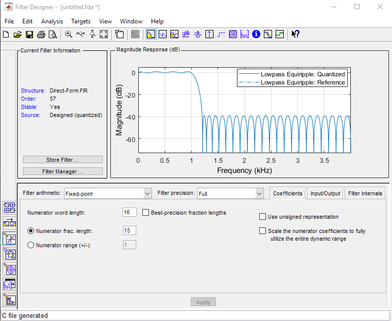
The coefficients can be exported from Matlab to C. As a reminder, the q15 data type has 15 fractional bits. During the generation of these C coefficients, the proper data type must be chosen to select the proper precision. The coefficient generation process results in the following output.
const int BL = 58;
const int16_T B[58] = {
     -232,    -47,    109,    319,    462,    430,    205,   -104,   -314,
     -278,     -1,    343,    504,    323,   -133,   -580,   -681,   -285,
      426,    990,    938,    132,  -1056,  -1847,  -1447,    478,   3523,
     6642,   8610,   8610,   6642,   3523,    478,  -1447,  -1847,  -1056,
      132,    938,    990,    426,   -285,   -681,   -580,   -133,    323,
      504,    343,     -1,   -278,   -314,   -104,    205,    430,    462,
      319,    109,    -47,   -232
};
We will now use these coefficients in a DMA-driven FIR filter. For comparison, we will use a direct C code implementation (interrupt driven), as well as an ARM CMSIS based implementation (dma driven) and compare the performance of both.
#include "xlaudio.h"
#include "xlaudio_armdsp.h"

#define BLOCKSIZE 8
#define NUMTAPS 58

q15_t taps[NUMTAPS + BLOCKSIZE - 1];
arm_fir_instance_q15 F;

typedef q15_t int16_T;

#include "fdacoefs.h"

void processBuffer(uint16_t x[BLOCKSIZE], uint16_t y[BLOCKSIZE]) {
    q15_t xq[BLOCKSIZE], yq[BLOCKSIZE];
    xlaudio_adc14_to_q15_vec(x, xq, BLOCKSIZE);
    arm_fir_q15(&F, xq, yq, BLOCKSIZE);
    xlaudio_q15_to_dac14_vec(yq, y, BLOCKSIZE);
}

// This is the interrupt-based (per-sample) filter operation for comparison
// Note that you cannot simultaneously run the DMA-based scheme and interrupt-based scheme
uint16_t processSample(uint16_t x) {
      q15_t v = xlaudio_adc14_to_q15(x);
      taps[0] = v;
      int i;
      q15_t q = 0;
      for (i=0; i<NUMTAPS; i++)
          q = q + (taps[i] * B[i] >> 15);
      for (i=NUMTAPS-1; i>0; i--)
          taps[i] = taps[i-1];
      return xlaudio_q15_to_dac14(q);
}


#include <stdio.h>

int main(void) {
    WDT_A_hold(WDT_A_BASE);

    arm_fir_init_q15(&F, NUMTAPS, (int16_t *) B, taps, BLOCKSIZE);

    xlaudio_init_dma(FS_8000_HZ, XLAUDIO_J1_2_IN, BUFLEN_8, processBuffer);
    uint32_t c = xlaudio_measurePerfBuffer(processBuffer);
    printf("DMA Cycles: %d\n", c);

    // This is what you'd write in an interrupt-driven IO scheme:
    //
    //        xlaudio_init_intr(FS_8000_HZ, XLAUDIO_J1_2_IN, processSample);
    //        uint32_t c = xlaudio_measurePerfSample(processSample);
    //        printf("INT Cycles: %d\n", c);

    xlaudio_run();

    return 1;
}
The
int16_Tdata type created by matlab can be equated with aq15_t.The traditional implementation is shown in
processSample. Note the scaling of the multiplication by 15 bits, when we multiply q15*q15 and accumulate in a q15. The run theprocessSampleversion, uncomment thexlaudio_init_intrcall in the main function (and comment out thexlaudio_init_dmacall).In the DMA version, the
processSampleis replaced with aprocessBufferfunction, which filters a block of samples. The XLAUDIO_LIB has functions to convert a vector of samples from the ADC/to the DAC to internal q15, f32 or q31 datatype.The
mainfunction creates a DMA block-based setup rather than an interrupt-driven sample-based setup. The key parameter isBLOCKSIZE, which describes the blocksize used by the DMA.
When this function is compiled with Global Optimization (level 2) at setting 3 for the speed-vs-size trade-off, we find that 7625 cycles are needed per DMA block (8 samples) while 1850 cycles are needed per interrupt (sample). Hence, the DMA version uses about 953 cycles per sample, which is a considerable improvement. The bulk of this improvement comes from the internal design of arm_fir_q15. You can find the source code of arm_fir_q15 on the source tree of the MSP432 software support package (simplelink_msp432p4_sdk_3_40_01_01/source/third_party/CMSIS/DSP_Lib/Source/FilteringFunctions).
IIR Designs using ARM CMSIS DSP
Just as with FIR, there are several IIR variants in ARM CMSIS DSP. We illustrate a few examples that use single-precision floating point data types. There, of course, variants that use fixed-point precision data types as well. The full list can be found online. We will discuss Direct Form II Transpose Cascade.
The following is an example of a IIR Direct Form II Transpose Cascade with float32_t coefficients.
Important
void arm_biquad_cascade_df2T_f32   (   const arm_biquad_casd_df1_inst_f32 *    S,
                                      const float32_t *   pSrc,
                                      float32_t *     pDst,
                                      uint32_t    blockSize
                                  )
Parameters
[in]
Spoints to an instance of the float32_t biquad cascade structure[in]
pSrcpoints to the block of input data[out]
pDstpoints to the block of output data[in]
blockSizenumber of samples to process
Returns
none
The data structure that holds the coefficients, arm_biquad_casd_df2T_inst_f32, is organized in cascade sections as follows (online reference):
typedef struct
{
  uint32_t numStages;
  float32_t *pState;
  const float32_t *pCoeffs;
} arm_biquad_cascade_df2T_instance_f32;
numStages holds the number of second-order-sections.
pState is an array with state elements, and there are 2 times numStages state elements. The order of state elements is v[n-1], v[n-2].
pCoeffs is an array of 5 times numStages coefficients, each holding the coefficients of a single cascade stage. The order of coefficients are b0, b1, b2, a1, a2, each time repeated per cascade stage.
Let’s go through the example of an IIR design with the following specifications. The sample rate is 8KHz, the passband is 950Hz to 1050Hz with less than 1dB ripple. The lower stopband ends at 800Hz, and the higher stopband starts at 1100Hz. The stopband suppression must be better than 40dB. Matlab filterDesigner can translate these specs into an 8th-order IIR filter which can be decomposed into four second-order sections.
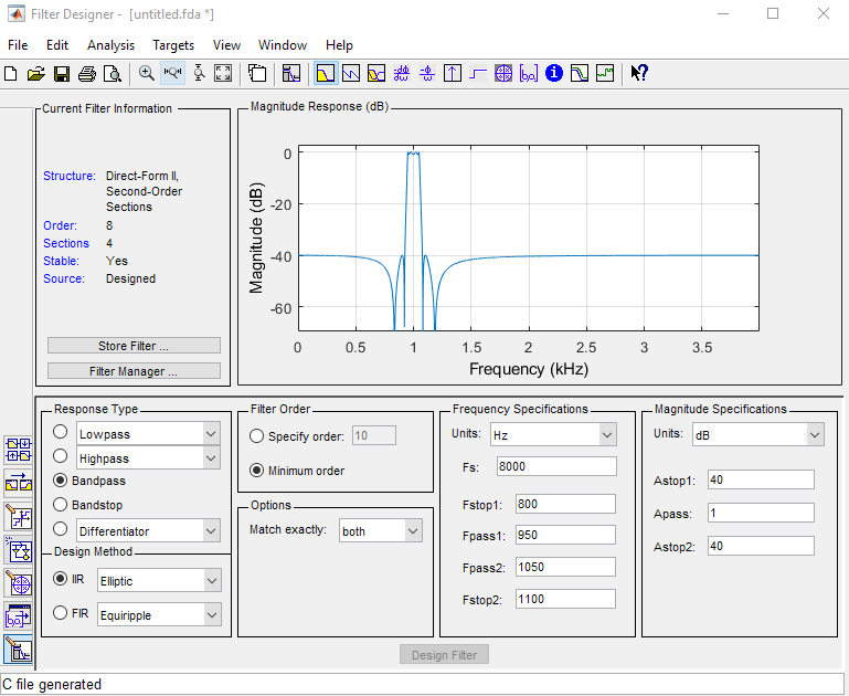
As with the FIR filter design, we extract the filter coefficient from Matlab by generating a C header. In this case, the precision of the generated coefficients can be single-precision floating-point, as we target an arm_biquad_casd_df1_inst_f32 filter which uses single-precision floating-point coefficients. This data structure has be reformatted somewhat to match the ARM CMSIS expectations for the arm_biquad_casd_df1_inst_f32 data structure; we will include the translation as part of the program.
#include "xlaudio.h"
#include "xlaudio_armdsp.h"

// coefficients produced using Matlab filterDesigner

typedef float32_t real32_T;

#include "fdacoefs.h"

// number of cascade sections
#define NUMSECTIONS 4
float32_t taps[2 * NUMSECTIONS];
float32_t coefficients[5 * NUMSECTIONS];

// shown as a function to illustrate how matlab format
// maps to ARM CMSIS format. For the most compact
// implementation, you would precompute this mapping
// and initialize coefficients as a constant array

void mat2armdsp() {
    coefficients[0]  =  NUM[0][0] * NUM[1][0];
    coefficients[1]  =  NUM[0][0] * NUM[1][1];
    coefficients[2]  =  NUM[0][0] * NUM[1][2];
    coefficients[3]  = -DEN[0][0] * DEN[1][1];
    coefficients[4]  = -DEN[0][0] * DEN[1][2];
    coefficients[5]  =  NUM[2][0] * NUM[3][0];
    coefficients[6]  =  NUM[2][0] * NUM[3][1];
    coefficients[7]  =  NUM[2][0] * NUM[3][2];
    coefficients[8]  = -DEN[2][0] * DEN[3][1];
    coefficients[9]  = -DEN[2][0] * DEN[3][2];
    coefficients[10] =  NUM[4][0] * NUM[5][0];
    coefficients[11] =  NUM[4][0] * NUM[5][1];
    coefficients[12] =  NUM[4][0] * NUM[5][2];
    coefficients[13] = -DEN[4][0] * DEN[5][1];
    coefficients[14] = -DEN[4][0] * DEN[5][2];
    coefficients[15] =  NUM[6][0] * NUM[7][0];
    coefficients[16] =  NUM[6][0] * NUM[7][1];
    coefficients[17] =  NUM[6][0] * NUM[7][2];
    coefficients[18] = -DEN[6][0] * DEN[7][1];
    coefficients[19] = -DEN[6][0] * DEN[7][2];
}

arm_biquad_cascade_df2T_instance_f32 F;

#define BLOCKSIZE 8

void processBuffer(uint16_t x[BLOCKSIZE], uint16_t y[BLOCKSIZE]) {
    float32_t xf[BLOCKSIZE], yf[BLOCKSIZE];
    xlaudio_adc14_to_f32_vec(x, xf, BLOCKSIZE);
    arm_biquad_cascade_df2T_f32(&F, xf, yf, BLOCKSIZE);
    xlaudio_f32_to_dac14_vec(yf, y, BLOCKSIZE);
}

#include <stdio.h>

int main(void) {
    WDT_A_hold(WDT_A_BASE);

    mat2armdsp();
    arm_biquad_cascade_df2T_init_f32(&F, NUMSECTIONS, coefficients, taps);

    xlaudio_init_dma(FS_8000_HZ, XLAUDIO_J1_2_IN, BUFLEN_8, processBuffer);

    uint32_t c = xlaudio_measurePerfBuffer(processBuffer);
    printf("DMA Cycles: %d\n", c);

    xlaudio_run();

    return 1;
}
The matlab data type
real32_Tmaps directly intofloat32_tas defined inxlaudio_armdsp.h.The
tapsandcoefficientsdata structures hold the taps and coefficients of each section. Themat2armdspfunction illustrates how the matlab coefficients map into ARMCMSIS coefficients. Note the sign change for the feedback coefficients.The
processBufferfunction shows the processing of a DMA block. Similar as with the FIR design, conversion functions are used to convert a vector of ADC samples and DAC samples tofloat32_tand back.The
mainfunction includes an additional initialization call toarm_biquad_cascade_df1_init_f32to initialize the filter data stucture.At optimization level 2, setting ‘3’, this filter requires 6350 cycles per block of 8 samples or around 793 cycles per sample.
However, when the same IIR functionality is processed using an interrupt-driven (per-sample) scheme, the resulting filter only uses 402 cycles per sample at the same optimization level. This relative inefficiency of the ARM CMSIS code is interesting but would require further study of the source code (simplelink_msp432p4_sdk_3_40_01_01/source/third_party/CMSIS/DSP_Lib/Source/FilteringFunctions). At least, this demonstrates that performance improvement by using external libraries is not unconditional. Performance evaluation is always needed!
Conclusions
We discussed the use of a DSP library with a standard API called ARM CMSIS DSP. Combined with a DMA-based I/O scheme, this library provides an optimized implementation of many filter constructions. We will use ARM CMSIS DSP regularly in the coming labs.