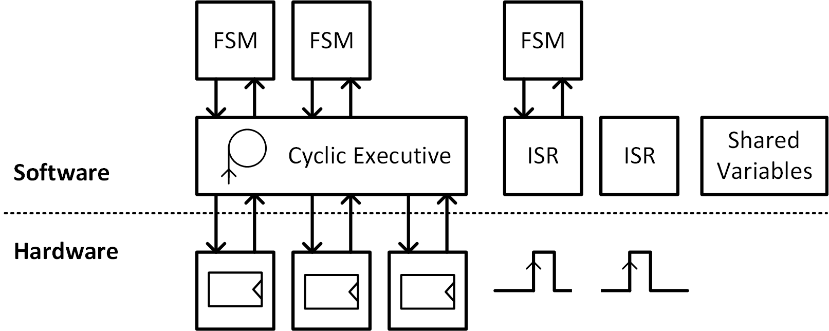
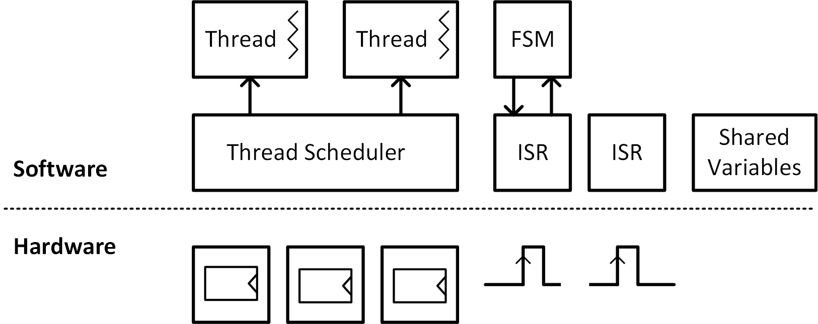
As a spin-off from my ECE2534 class (Microcontroller Interfacing), I’m trying to define a template design for low-level microcontroller software. This leads to a family tree with three types of software machines: the event machine, the event sequence machine and the threaded event sequence machine. A previous post discusses the event machine. This post discusses the latter two types.
The event sequence machine

To see the need for an event sequence machine as opposed to an event machine, let’s recap the basic layout of the event machine. The event machine is a simple and straightforward layout for a micro-controller program. It uses a tight while loop, the cyclic executive, which repeatedly scans the microcontroller inputs to detect and to respond to hardware events. It also uses interrupt service routines (ISRs) to tie hardware events directly to function calls. This event machine is very good to develop simple event-response software. The event machine maps every event to a unique and well-defined response. An example of such a one-to-one mapping is the event of a UART receiving a character, which is mapped into a software response that stores the character in a memory buffer.
The event machine is not very well suited to detect a sequence of events. This is because the model of the cyclic executive cannot remember if a hardware event occurred previously or not; the cyclic executive only detects immediate events. The lack of memory is a challenge, and there are many situations where context matters. The following is an example of such a design problem. As before, it is an application for a MSP430FR5994 Launchpad. The Launchpad has two buttons, B1 and B2, as well as two LEDs, LED1 and LED2. Now consider the following control problem.
- LED1 should toggle when one presses B2 and next B1 (without releasing B2).
- LED2 should toggle when one presses B1 and next B2 (without releasing B1).
While this problem is easy to explain, it’s not easy to program it as an event machine. Indeed, to decide when a LED should turn on or turn, we have to detect two separate events. First, a button has to be closed while the other is still open. Next, both buttons have to be closed.
Here is an attempt at programming this problem using an event machine. It’s an intuitive but poor solution, and I’m including it here because it is unfortunately quite common to see this style of coding from students in the Microcontroller Class (ECE 2534).
   #include <driverlib.h>

   unsigned button1pressed() {
     return (GPIO_getInputPinValue(GPIO_PORT_P5, GPIO_PIN6) == 0);
   }

   unsigned button2pressed() {
     return (GPIO_getInputPinValue(GPIO_PORT_P5, GPIO_PIN5) == 0);
   }

   int main(void) {

     WDT_A_hold(WDT_A_BASE);

     GPIO_setAsOutputPin(GPIO_PORT_P1, GPIO_PIN0); // LED 1
     GPIO_setAsOutputPin(GPIO_PORT_P1, GPIO_PIN1); // LED 2
     GPIO_setAsInputPinWithPullUpResistor (GPIO_PORT_P5, GPIO_PIN6); // PB 1
     GPIO_setAsInputPinWithPullUpResistor (GPIO_PORT_P5, GPIO_PIN5); // PB 2
     PMM_unlockLPM5();

     while(1) {

        if (button1pressed()) {
            // Button 1 press detected
            while (! button2pressed())
                ; // wait for Button 2
            GPIO_setOutputHighOnPin(GPIO_PORT_P1, GPIO_PIN0);
        } else
            GPIO_setOutputLowOnPin(GPIO_PORT_P1, GPIO_PIN0);

        if (button2pressed()) {
            // Button 2 press detected
            while (! button1pressed())
                ; // wait for Button 1
            GPIO_setOutputHighOnPin(GPIO_PORT_P1, GPIO_PIN1);
        } else
            GPIO_setOutputLowOnPin(GPIO_PORT_P1, GPIO_PIN1);

     }
   }
This program detects the second button press by means of a nested while loop, and this is a problem. Once a first button press is detected, the cyclic executive blocks waiting for the second button press. For example, after detecting button B1, a while loop blocks while waiting for B2.
The blocking behavior causes two problems. First, the program cannot handle the case when a button is pressed and immediately released again. Second, the blocking behavior breaks a key principle of the cyclic executive, namely that the hardware inputs should be continuously scanned as fast as possible in order to create the illusion of concurrency.
There’s a better solution for design problems that involve event sequences. A finite state machine, in combination with an event machine leads to an event sequence machine. Let’s first evaluate how a finite state machine can solve the button pressing sequence problem. The inputs of the finite state machine are the events. Button 1 can be pressed (B1) or released (!B1). Similarly, button 2 can be pressed (B2) or released (!B2).
LED1 should toggle when one presses B2 and next B1 (without releasing B2). The following FSM detects the correct sequence.
FSM1:
  state S0, S1, S2
  input B1, B2

  S0:
     if (B2 & !B1) goto S1
     else goto S0

  S1:
     if (B1 & B2) goto S2
     else if (B2) goto S1
     else goto S0

  S2:
     goto S0
There’s a similar FSM to detect the sequence that will light up LED2. A finite state machine can be captured in a C function that accepts the events as input arguments, and that returns the current state as output.
enum tState {s0, s1, s2};
enum tState fsm1(unsigned B1, unsigned B2) {
   static enum tState state = s0;
   switch (state) {
      case s0:
        if (B1 & !B2)
            state = s1;
        break;
      case s1:
        if (B1 & B2)
            state = s2;
        else if (!B1)
            state = s0;
        break;
      case s2:
        state = s0;
        break;
    }
    return state;
}
Note that the finite state machine behaves as a function call that returns immediately. The function does not block in a while-loop and does not wait for an event to appear. The finite state ‘remembers’ its position in an event sequence by remembering its current state.
Once the finite state machine is available, the cyclic executive can integrate the calls to the finite state machine as one of the event actions.
#include <driverlib.h>

unsigned button1pressed() {
  return (GPIO_getInputPinValue(GPIO_PORT_P5, GPIO_PIN6) == 0);
}

unsigned button2pressed() {
  return (GPIO_getInputPinValue(GPIO_PORT_P5, GPIO_PIN5) == 0);
}

enum tState {s0, s1, s2};

enum tState fsm1(unsigned B1, unsigned B2) {
   static enum tState state = s0;
   switch (state) {
      case s0:
        if (B1 & !B2)
            state = s1;
        break;
      case s1:
        if (B1 & B2)
            state = s2;
        else if (!B1)
            state = s0;
        break;
      case s2:
        state = s0;
        break;
    }
    return state;
}

enum tState fsm2(unsigned B1, unsigned B2) {
   static enum tState state = s0;
   switch (state) {
      case s0:
        if (B2 & !B1)
            state = s1;
        break;
      case s1:
        if (B2 & B1)
            state = s2;
        else if (!B2)
            state = s0;
        break;
      case s2:
        state = s0;
        break;
    }
    return state;
}

int main(void) {

   WDT_A_hold(WDT_A_BASE);

   GPIO_setAsOutputPin(GPIO_PORT_P1, GPIO_PIN0); // LED 1
   GPIO_setAsOutputPin(GPIO_PORT_P1, GPIO_PIN1); // LED 2
   GPIO_setAsInputPinWithPullUpResistor (GPIO_PORT_P5, GPIO_PIN6); // PB 1
   GPIO_setAsInputPinWithPullUpResistor (GPIO_PORT_P5, GPIO_PIN5); // PB 2
   PMM_unlockLPM5();

   while(1) {

      unsigned B1 = button1pressed();
      unsigned B2 = button2pressed();

      if (FSM1(B1, B2))
          GPIO_toggleOutputOnPin(GPIO_PORT_P1, GPIO_PIN0);

      if (FSM2(B1, B2))
          GPIO_toggleOutputOnPin(GPIO_PORT_P1, GPIO_PIN1);
   }
}
Finite state machines integrated into the cyclic executive are clearly better suited to detect a sequence of events. The figure on top of this post illustrates how an event machine is converted into an event sequence machine, by adding a layer of finite state machines on top of the cyclic executive. Furthermore, Interrupt Service Routines (ISR) can be combined with finite state machines as well. The essence, however, is to understand the role of finite state machines. They are able to remember (and recall) a position in a sequence of control steps.
Finite state machines are extensively used by hardware designers, but they are perhaps a bit foreign to software designers. In addition, the software implementation of finite state machines is not very clear or elegant - they rely on case statements that have one entry for every state. It’s not uncommon for a complex finite state machine to extend over hundreds of lines of code in C. In other words: finite state machines, written in C, are not very scalable nor readable. The final software structure we’ll discuss is the ‘threaded event sequence machine’, and that machine deals with the problem of finite state machines.
The threaded event sequence machine

It’s worthwhile to reconsider the blocking solution in a cyclic executive. We rejected blocking because it temporarily blinds the microcontroller for other hardware events that may occur. Suppose that the microcontroller would have to recognize three different event sequences, concurrently, then it would have to be able to test for three different hardware events at any one time. And for this reason, the nested while-loop is considered a clumsy solution.
        if (button1pressed()) {
            // Button 1 press detected
            while (! button2pressed())
                ; // wait for Button 2
            GPIO_setOutputHighOnPin(GPIO_PORT_P1, GPIO_PIN0);
        } else
            GPIO_setOutputLowOnPin(GPIO_PORT_P1, GPIO_PIN0);
However, logically, a nested while loop makes perfect sense. If we would like to detect a button press on B1 followed by a button press on B2, then that’s what we should be able to write in C.
We will use a solution that is able to follow multiple logical paths in a program at the same time. Each such logical path is called a thread of control. And the threaded event sequence engine is a template that can handle multiple threads of control. Control threading is not natively supported in C, and it requires the use of an external library. I’ll be making use of protothreads, a threading library especially suited for microcontrollers. It doesn’t have all the bells and whistles of a heavyweight library such as pthreads, but it’s perfectly adequate for managing event sequence detection.
     #include <driverlib.h>
 #include "pt.h"

 unsigned button1pressed() {
    return (GPIO_getInputPinValue(GPIO_PORT_P5, GPIO_PIN5) == 0);
 }

 unsigned button2pressed() {
    return (GPIO_getInputPinValue(GPIO_PORT_P5, GPIO_PIN6) == 0);
 }

 static int protothread1(struct pt *pt) {
   PT_BEGIN(pt);
   while (1) {
     PT_WAIT_UNTIL(pt,  button1pressed() && !button2pressed());
     PT_WAIT_UNTIL(pt, !button1pressed() ||  button2pressed());
     if (button1pressed())
         GPIO_toggleOutputOnPin(GPIO_PORT_P1, GPIO_PIN0);
   }
   PT_END(pt);
 }

 static int protothread2(struct pt *pt) {
   PT_BEGIN(pt);
   while (1) {
     PT_WAIT_UNTIL(pt,  button2pressed() && !button1pressed());
     PT_WAIT_UNTIL(pt, !button2pressed() ||  button1pressed());
     if (button2pressed())
         GPIO_toggleOutputOnPin(GPIO_PORT_P1, GPIO_PIN1);
   }
   PT_END(pt);
 }

 int main(int argc, char** argv) {
   static struct pt pt1, pt2;

   WDT_A_hold(WDT_A_BASE);

   GPIO_setAsOutputPin(GPIO_PORT_P1, GPIO_PIN0); // LED 1
   GPIO_setAsOutputPin(GPIO_PORT_P1, GPIO_PIN1); // LED 2
   GPIO_setAsInputPinWithPullUpResistor (GPIO_PORT_P5, GPIO_PIN6); // PB 1
   GPIO_setAsInputPinWithPullUpResistor (GPIO_PORT_P5, GPIO_PIN5); // PB 2
   PMM_unlockLPM5();

   PT_INIT(&pt1);
   PT_INIT(&pt2);

   while(1) {
     protothread1(&pt1);
     protothread2(&pt2);
   }

 }
This program starts two threads, each of them captured in a separate function. Each of these functions is a proper while loop by itself, which can block for a specific button to be pressed. However, because of the threading library, control can be passed from one while loop to the other. That is when a statement such as
PT_WAIT_UNTIL(pt, button2pressed());
is encountered, and button B2 is not pressed, then the thread will suspend execution and the execution continues in another thread.
The Figure above shows a schematic for a threaded event sequence machine. ISRs cannot be written as threads, and it’s against the spirit of an ISR to develop it as such.
