Lab 2: Implementation of FIR filters
The purpose of this assignment is as follows.
to familiarize you with the filter design tools in Matlab,
to familiarize you with the basic calibration of signal values captured using AUDIO BOOSTXL,
to familiarize you with the implementation of finite impulse reponse (FIR) filtering using MSP-EXP432P401R,
to compare the performance of various FIR implementation styles.
Attention
To handle the portability and/or SimpleLink installation issues, the software configuration of Lab 2 has been simplified as follows. The xlaudio library is integrated into the Lab 2 source code. This makes the project standalone. In addition, the distribution is hardcoded for the following environment.
Windows 10
Code Composer Studio 10.4.0.00006 installed in
c:\ti\ccs1040MSP432 SimpleLink SDK 3.40.01.02 installed in
c:\ti\simplelink_msp432p4_sdk_3_40_01_02
If your environment is different (different OS, different CCS), then you should verify and possibly update the following settings after downloading the lab projects:
Under Project - Properties, select Arm Compiler - Include Options. In the first box (search path), verify and possibly update the following entries:
C:/ti/simplelink_msp432p4_sdk_3_40_01_02/sourceC:/ti/simplelink_msp432p4_sdk_3_40_01_02/source/third_party/CMSIS/IncludeNext, under Project - Properties, Select Arm Linker - File Search Path. In the second box (library search path), verify and possibly update the following entry
C:/ti/simplelink_msp432p4_sdk_3_40_01_02/source/ti/devices/msp432p4xx/driverlib/ccsA final check is to verify the compiler version selected by your installation. Under Project - Properties, select CCS General. Verify the compiler version as TO v20.2.5.LTS. If your CCS don’t has that compiler, CCS will find the closest match and use that one instead. Resolving a mismatch may require installing a new compiler. Contact the instructor or tutor if that is the case.
Finite Impulse Response Filter
An FIR filter with M taps is a digital filter described by the following input/output relationship
![y[n] = \sum_{k=0}^{M-1} b[k] x[n-k]](_images/math/8b56cb7450003d26bb59b4acd1e427585ceff747.png)
where ![y[n]](_images/math/e715df3dbb5eddf44ee2af44f4e1ec5ed7588628.png) is the current filter output,
is the current filter output, ![b[0],...,b[M-1]](_images/math/bbb0870d6dd5815b5fb6b4e03fea58c174d905d4.png) are the
feedforward filter coefficients, and
are the
feedforward filter coefficients, and ![x[n],...,x[n-M+1]](_images/math/ed82cba0fcc60c518aeb67a15f47aa97caab15c2.png) are the current input
and
are the current input
and  previous inputs. The inputs are stored in a buffer referred to as the
taps of the FIR filter.
previous inputs. The inputs are stored in a buffer referred to as the
taps of the FIR filter.
To compute the very first filter output ![y[0]](_images/math/3d3b191234d7731ca67cbe3bb34635b35f991e51.png) using the very first
input
using the very first
input ![x[0]](_images/math/7ca6d5188a59848660c6e382a450d2ab200b26b3.png) , one must assume an initial value for
, one must assume an initial value for ![x[-1],...,x[-M+1]](_images/math/280d1d59f485363b0f0a737ff8d7375442ed8953.png) .
In this lab we will assume that the initial value of the taps of the FIR filter is 0.
.
In this lab we will assume that the initial value of the taps of the FIR filter is 0.
This lab is focused on the implemention of the formula to compute an FIR output using a DSP program in C. We are primarily concerned with the correct implementation of the FIR design using floating-point precision. In a later assignment, we will study the optimized implementation of the FIR design using fixed-point arithmetic.
Finite Impulse Response Filter Specifications
In this lab you will develop an implementation for an FIR filter with the following specifications.
You will design a lowpass filter with a cutoff of 941 Hz and a stop band of 1209 Hz. The maximum passband rippple is 1dB, and the required stopband rejection is 45 dB. You may recognize that the frequencies 941 Hz and 1209 Hz are not arbitrarily chosen. These frequencies correspond to the highest DTMF row frequency and the lowest DTMF column frequency. This filter can thus be used to split the row signal from the overall DTMF signal. The 45 dB stopband rejection corresponds to the typical signal to noise ratio on a telephone line.
You can pick any supported sample rate and any filter design method you like, as long
as your design meets all of the filter design requirements including real-time performance.
You can use Matlab filter design tools such as filterDesigner to create the coefficients
for your FIR filter. The Matlab filter design tools allow you to analyze various aspects of
your filter such as its impulse response, frequency response, and pole-zero plot, among others.
The Matlab filter design tools allow you to export the filter coefficients as a C header
file. You can use these generated coefficients directly in your program. You will perform all
calculations in this assignment using single-precision floating point numbers.
Note
C recognizes multiple floating-point precision
levels, and the most common ones are single-precision floating point (float) and double-precision floating
point (double). Single-precision floating point is a 32-bit datatype (a sign bit, 8 exponent bits and 23 mantissa bits),
while double-precision floating
point commonly uses 64 bits.
A floating-point constant can be written in various ways. For example, the value 0.75 can be written as
0.75 or 75e-2 or .0075e2. Without a floating-point suffix, such a constant is treated as
having double precision. The floating-point suffix f can be added to indicate the compiler that
you are providing a single-precision floating constant. Thus, the value 0.75 as a single-precision
constant can be written as 0.75f or 75e-2f.
In filterDesigner, coefficients can be generated as single-precision floating point, double-precision floating point, and even fixed-point. The single-precision floating point data type used by filterDesigner is real32_T, while the same data type in our program (and in the ARM CMSIS standard) is called float32_t. You’ll have to make sure to add a definition that equates the two data types, or modify the C file generated by Matlab.
Calibration
Before you will develop your real-time DSP filter, you first have to gain insight into the calibration of analog signals into digital floating point numbers. The MSP-EXP432P401R Launchpad used for your course project contains a 14-bit Analog to Digital Converter, which converts analog voltages between 0 volts and 3.3 volts (full scale). The processed signal from the MSP432 processor is converted through digital audio using a 14-bit Digital to Analog Converter integrated on the Audio Signal Processing Boosterpack. The DAC converts digital codes to analog voltages between 0 volts and 3.3 volts (full scale).
The following figure illustrates the calibration of analog values to digital numbers. The ADC produces
14-bit numbers which are mapped into a 16-bit unsigned data type. These integers are converted into
single-precision floating-point numbers using float32_t xlaudio_adc14_to_f32(uint16_t), a function
provided in XLAUDIO_LIB. The lowest ADC value (0) is mapped to the real value -0.25, and
the highest ADC value (0x3FFF) is mapped to the real value 0.25. A floating point number can be
converted back to a voltage by first converting the number to a 16-bit unsigned integer
using uint16_t xlaudio_f32_to_dac14(float32_t), and next sending that number to the 14-bit DAC.
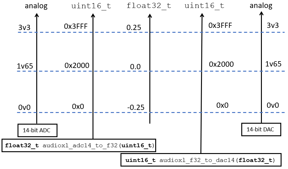
Calibration Chart relating analog values, DAC/ADC values, and floating point values
We recall how a typical real-time DSP program looks like. We demonstrate the case of an interrupt-driven sample conversion with a 8 KHz sample rate.
 1#include "xlaudio.h"
 2
 3uint16_t processSample(uint16_t x) {
 4   float32_t v = adc_to_f32(x);
 5
 6   // ... DSP code goes here
 7
 8   return f32_to_dac(v);
 9}
10
11int main(void) {
12    WDT_A_hold(WDT_A_BASE);
13
14    xlaudio_init_intr(FS_8000_HZ,
15                      XLAUDIO_J1_2_IN,
16                      processSample);
17    xlaudio_run();
18
19    return 1;
20}
Important
Question 1: Create a DTMF signal for any of the 16 keys of the DTMF keypad.
Your DTMF key code must be programmable as a constant in the program.
Your DTMF waveform must be calibrated such that a single sine waveform of the DTMF signal measures 1.2V peak-to-peak.
The left key of the LaunchPad board must be configured as follows. When no key is pressed, both the row sine wave and the column sine wave will included in the output waveform. When the left key is pressed, only the row sine wave will be included.
You may make use of the dtmf_generator code discussed in the first week of class. You can make use of the XLAUDIO_LIB functions, for example to read the state of the buttons.
In your answer, include a screen shot of a DTMF waveform (both sines included), a screen shot of the row-sine by itself, and a screenshot of the column-sine by itself. Demonstrate that the signal has the required amplitude.
Filter Coefficient Generation
Use the Matlab filterDesigner tool to create a FIR according to the passband specifications provided
earlier. You can choose any suitable sample frequency as long as it yields a filter that meets the passband
specifications.
Important
Question 2: Generate floating point coefficients that can be included in a C file.
When your design is complete, extract the following information from filterDesigner:
the filter’s impulse response, the filter’s amplitude response, the filter’s phase response,
and the filter’s pole-zero plot. You will include these plots in your report.
Filter Implementation: FIR Direct Form
Implement a Direct-Form FIR filter using the coefficients created earlier.
The first implementation is the so-called Direct Form implementation, illustrated in the figure below.
You will have to adjust the number of taps of the filter to the number identified by the Matlab
filter design program. Call this function processSampleDirect.
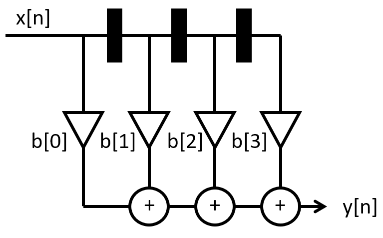
Direct Form FIR filter
To test the filter, integrate your code for question 1 into the FIR filter, such that the input
for the FIR filter is taken from your DTMF generator. Essentially, the DAC code that is sent
to the DAC in the program of question 1, will be used as the ADC input code for processSampleDirect.
You can integrate the DTMF signal generation the FIR filter directly in software (i.e., processSampleDirect handles DTMF signal generation as well as FIR filtering).
The following configuration of the pushbuttons will make testing easy.
When no button is pressed, a DTMF signal containing both row and column frequency are fed into the filter, and the filter output is send to the speaker.
When the left button is pressed, only the row frequency is fed into the filter, and the filter output is send to the speaker.
When the right button is pressed, the DTMF signal containing both row and column frequency is send directly to the speaker, without filtering.
Note
Getting a complex filter operation to work ‘out of the box’ is challenging, so if the filter does not work as described above, don’t despair. You can work systematically through the design to make sure that everything works as expected. Here are some tips.
First, the MSP432EXP401R does not have a straightforward error reporting. One of the first, basic
tests that you can do, is to verify that the program is running. The DAC_SYNC, which
toggles once for every two bytes transmitted to the DAC, enables you to verify that
there is digital data moving from the MSP432EXP401R microcontroller to the DAC on the
Audio BoostXL board. To measure this signal, connect an oscilloscope probe to
pin D sync on header J2 of the Audio BoostXL board. If you don’t observe a DAC sync
pulse, but you believe that there should be one, then the MSP432EXP401R may have suffered
an exception – which halts execution of the DSP program. Such an exception typically
occurs when you have an out-of-bounds array access.
Second, if the program is running, but you don’t get any output, you may need to observe
the signal being send to the audio amplifier. Refer to Connecting the Oscilloscope to check where
you need to connect the oscilloscope probe. Once the oscilloscope is connected you can
perform simple tests - such as applying 0v or 3V3 to the input pin XLAUDIO_J1_2_IN,
and verifying that the output level of the DAC reacts correspondingly. Work systematically
through the signal processing chain from the input to the output. Verify your work
frequently and make small modifications at a time.
Finally, you can rely on the source-level debugger included in Code Composer Studio. However, since the source-level debugger essentially halts the real-time behavior of the program (masking further interrupts etc), this debugging technique is not very helpful to identify issues related to the real-time nature of the processing.
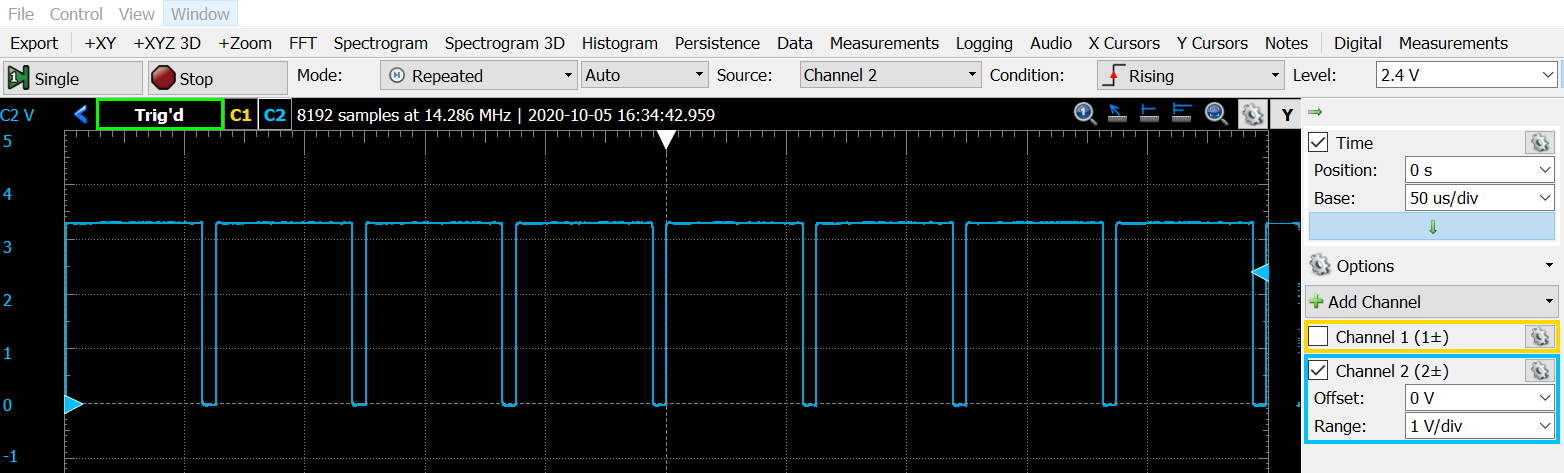
DAC SYNC of an audio stream at 16KHz sample rate
Attention
Make sure that the sample rate of the output signal (as measured through the DAC SYNC) is the same as the sample frequency you will choose for your filter. If your filter is too slow, optimize the C code. You can also enable the compiler optimization (under Project Properties -> CCS Build -> Arm Compiler -> Optimization)
Measuring the performance of the FIR filter
The performance of the FIR filter is the amount of clock cycles required to process a
single signal sample. The total amount of clock cycles available to process a sample
equals 48 MHz / sample frequency. For example, at 16KHz there are 3000 clock cycles
available for each sample. Hence, it is important to understand how much computation
effort is needed to process one sample.
The XLAUDIO_LIB has a built-in function to compute the performance for you:
uint32_t xlaudio_measurePerfSample(msp432_sample_process_t _cb). Study the source code of
this function to understand how it works. You would typically
call xlaudio_measurePerfSample during
the initialization phase of the program, before you start the signal processing loop.
The return of this function is the number of clock cycles needed to complete the function.
You can printf this number and read it from the console in the debugger of
Code Composer Studio.
Important
Question 3: Write the C function that computes the FIR using Direct Form. You have to report the following data for this function:
The source code listing of
uint16_t processSampleDirect(uint16_t x)The performance of the implementation
The amplitude response of the FIR filter expressed as two screen shots showing the response of the FIR filter to a DTMF signal (a) containing both row and column frequencies; (b) containing only row frequency.
Filter Implementation: Optimizing the FIR Direct Form
Closely study the filter coefficients. Optimize your filter design for performance by exploiting the symmetry available in the filter coefficients.
Once you made the necessary modifications, repeat the same measurements as above: measure the frequency spectrum of the filter, and the performance of the filter.
Important
Question 4: Write the C function that optimizes the FIR direct form. You have to report the following data for this function:
The source code listing of
uint16_t processSampleDirectOptimized(uint16_t x)The performance of the implementation
The amplitude response of the FIR filter expressed as three screen shots showing the response of the FIR filter to a DTMF signal (a) containing both row and column frequencies; (b) containing only row frequency and (c) containing only column frequency.
Filter Implementation: The FIR Transpose Form
The following transformation of the filter is called the Transpose Form. It is functionally identical to the Direct Form (with the same coefficients), but it stores intermediate results in the filter taps, rather then the previous input values.
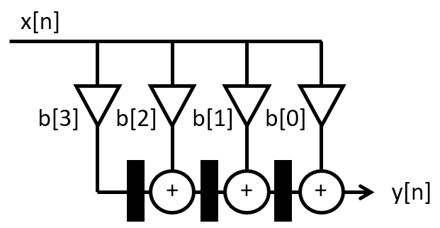
Transpose Form FIR
Implement this filter and perform the same measurements as you did for the other two filters.
Important
Question 5: Write the C function that optimizes the FIR transpose form. You have to report the following data for this function:
The source code listing of
uint16_t processSampleTranspose(uint16_t x)The performance of the implementation
The amplitude response of the FIR filter expressed as two screen shots showing the response of the FIR filter to a DTMF signal (a) containing both row and column frequencies; (b) containing only row frequency.
Wrapping Up
The answer to this lab consists of a written report which will be submitted on Canvas by the deadline. Refer to the General Lab Report Guidelines for details on report formatting. You will only submit your written report on Canvas. All code developed must be returned through github.
Not everybody in the class may be using the same setup to make oscilloscope measurements. Start your report with a short introduction on your measurement setup including the MSP-EXP432P401R kit, the oscilloscope and the signal generator that you have used for this lab.
Follow the five questions outlined above to structure your report. Optionally answer the bonus question. Use figures, screenshots and code examples where appropriate. Please work out the answers in sufficient detail to show your analysis.
Make sure that you add newly developed projects to your github repository. Further, make sure that you commit and push all changes to the github repository on GitHub classroom. Use the Team - Commit pop-up menu and push all changes.
Be aware that each of the laboratory assignments in ECE4703 will require a significant investment in time and preparation if you expect to have a working system by the assignment’s due date. This course is run in “open lab” mode where it is not expected that you will be able to complete the laboratory in the scheduled official lab time. It is in your best interest to plan ahead so that you can use the TA and instructor’s office hours most efficiently.
Good Luck
Grading Rubric
Requirement |
Points |
|---|---|
Question 1 Analysis |
15 |
Question 2 Analysis |
15 |
Question 3 Analysis |
15 |
Question 4 Analysis |
15 |
Question 5 Analysis |
15 |
All projects build without errors or warnings |
5 |
Code is well structured and commented |
5 |
Git Repository is complete and up to date |
5 |
Overall Report Quality (Format, Outline, Grammar) |
10 |
TOTAL |
100 |