Lab 1: Introduction to the Lab Kit
The purpose of this assignment is as follows.
to familiarize you with the MSP-EXP432P401R hardware and BOOSTXL-AUDIO kit,
to familiarize you with the process of editing, compiling, and downloading software with Code Composer Studio,
to familiarize you with the process of debugging software and measuring audio signals,
to verify basic notions of signal sampling and reconstruction.
Note
As of October 2021, the MSP432P401R MCU is no longer manufactured. As a consequence, some of the documentation regarding the chip or the Launchpad will become harder to find. Refer to Data Sheets and User Guides for a list of relevant documents that are mirrored locally at WPI.
Hardware Setup
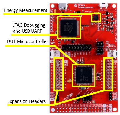
The MSP-EXP432P401R is a development kit for an MSP432P401R microcontroller. The microcontroller chip includes a 48MHz ARM Cortex M4 processor with floating point arithmetic unit, 64KB of SRAM (for variables) and 256KB of Flash memory (for code). The MSP432P401R includes a collection of hardware peripherals including a 14-bit Analog to Digital converter, among others. The board contains three chips, but only one of them, the DUT, will be used to run DSP programs. Two other microcontrollers are used to program the DUT, and to measure its energy consumption. The board also has two rows of expansion headers that can be used to fit additional boards.
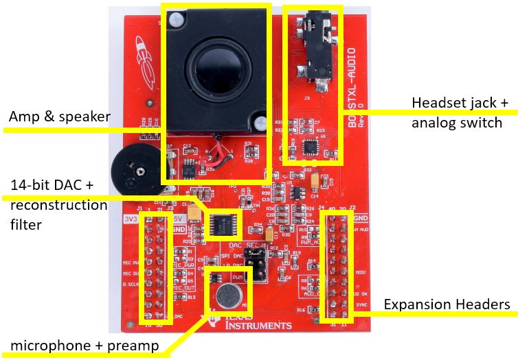
The audio interface for this board is implemented on a BOOSTXL-AUDIO board. This board includes a 14-bit Digital to Analog converter, audio amplifier and speaker, microphone with pre-amplifier. The board also has a jack for a headset, which will override the microphone and audio speaker with the headset audio.
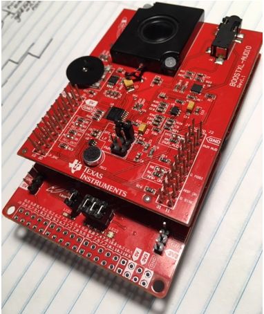
The expansion headers of the BOOSTXL-AUDIO board are compatible with the headers on the MSPEXP432P401R, and both boards can be connected together to yield the hardware configuration used for real-time DSP experiments. This combo takes one single connection through your computer using the micro-USB plug on the MSPEXP432P401R board. This USB connection provides power to both boards. To learn more about this setup, consult the MSPEXP432P401R User Guide pdf and the BOOSTXL-AUDIO User Guide pdf. These guides are useful to consult the connection details of the expansion headers, as well as the schematics of both boards available at the back of each user manual.
Software Setup
To complete this assignment, you will need to install the following software tools on your laptop.
You will also need to sign up for a GitHub account, in case you do not have one. All assignments in this course will be distributed as repositories and returned as updates on those repositories.
If you have never worked with version control and repositories before, take some time to learn about the basics of git repositories. The GitHub Guides contain several short tutorials in checking out, committing and pushing repositories. Code Composer Studio has built-in support for git repositories.
Note
The general sequence of solving an assignment will take the following practical steps.
You will navigate to a GitHub Classroom link which will create a personal repository for the assignment. Each assignment will have its own repository. This repository is private between you and the instructor and TA, meaning that only you, the instructor and the TA will have access to it.
You will download the assignment repository into CCS. The assignments typically will come with some starter code that you need to further complete while solving the assignment. Using CCS, you can develop code, compile code, download binary programs to the hardware kit, and debug programs running on the hardware kit.
When you have solved the assignment, you will upload the modifications that you made to the repository to GitHub. This can be done from within CCS. GitHub records the time of the upload. The assignment turn-in time will be the most recent update to your assignment repository.
Downloading the Assignment code in CCS
Important
Make sure that you understand the Lab and Report Teaming Policy before starting this lab. If you work in a team, make sure that every team member understands the rules and expectations for teamwork.
Start the assignment by clicking the GitHub Classroom link found in the table on the Labs page.
The link will create your private repository on the GitHub organization that serves this classroom. This private repository will be used to develop your solution for the lab.
Configure CCS for Github access by creating a public key
Attention
Before continuing, be sure to watch the video that demonstrates CCS and Github integration, including the generation of a public key. In particular, I strongly recommend to keep your CCS git repo’s and your CCS public key for Github access within the CCS Workspace.
The projects and examples in this course are distributed through GitHub. Code Composer Studio has built-in support for git repository access. There are two possible mechanisms to access a remote git repository. The first makes use of the HTTPS protocol, and requires you to type in your GitHub password. The second makes use of the SSH protocol, and requires you to configure a public key for your GitHub account.
We strongly recommend that you configure your GitHub account with a public key. This will help you save lots of precious time that is otherwise spent in typing passwords over and over.
Here are the steps you need to follow to configure a public key in your Github account.
Install openssh on your computer. For Windows, follow the instructions on Microsoft’s website. Complete the steps for an openssh client.
Open a powershell (Search - Windows Powershell). Type the command
ssh-keygenwhich will configure a public/private keypair in your account. By default this will bec:/users/username/.ssh/id_rsafor the private key andc:/users/username/.ssh/id_rsa.pubfor the public key. The default settings are OK. During creation of a keypair, the tool will ask you if you’d like to use a passphrase for your keypair. A passphrase is a password that protects your private key. Using a passphrase avoids that your private key is stored in plaintext format on your harddrive (better).Open the public key (
id_rsa.pub) in an editor. This will look something like this. Note that Windows thinks that ‘.pub’ files are files for Microsoft Publisher. Make sure to openid_rsa.pubwith an editor, not with Microsoft Publisher.
ssh-rsa AAAAB3NzaC1yc2EAAAABJQAAAYEA61OxYHJH/uDY8ZmxS/1H4hy4bk981+6ofbEbQQySSGYxhYGvfoVjasX6opVyOOm+uN2XnfCqetcjzEI7fddBhDe2tZzfTB+tvcL4rSu7cWQuCsG6pTgxdcEs5S1c6P/OWeNJRMCJTBr9FJjB+tsz8YAbasB83pZEkFZkVZmIM7VEyD6LfnijjpFKoaj4+ZjtfDf0Ra6fPirUS2kYCmuUQcbSmtxxDw8bVw667USOwQcbx+IX7SHMdsPT7edUIuiJR3MEZCeeoEZHaCDjEJoPfLT1dslBc8BmGWNt4XzoU1iq7Q32cdAavPCICl/KzN5EmH4LtWYnSiSyuc/mWKzvlUmFeB87fqqGu5a5+vv0c2lE0e5IOs8HoNFIqwghNw8gYu2LkT3yxZ+Bkv4+U4tT+OKdNblqXv4v1VqsWhs9BT4/I6I3tnWXmqaJdu0kwWi10FeqO8+VLNpHEb+CtNo/XCW75z+r2exmKvRZ5iqhO+H2ZsoexHsDAhsJ8pToHItd rsa-key-20210113
Open a webbrowser and access your GitHub account. Select Account - Settings - SSH and GPG Keys. Then select ‘New SSH Key’ and paste your public key into the text field. Give it a descriptive title, like ‘laptop access’.
You are now ready to check out repostories in CCS. When you provide a URL to import a git repository in CCS, make sure to select the SSH link, not the HTTPS link. For example:
// use this URL for SSH access
git@github.com:wpi-ece4703-b24/lab-1-patrickschaumont.git

// don't use this URL for SSH access
https://github.com/wpi-ece4703-b24/lab-1-patrickschaumont.git
Downloading the assignment repository
Copy the repository link that was created for your lab to the clipboard and start code composer studio. Take the following steps to download the repository into CCS.
In the project explorer pane, right-click and select Import .. from the pulldown menu, followed by Import.
A source selection window opens. Select Git and Projects from Git.
A repository selection window opens. Select Clone URI.
Enter the Team repository URI, as well as your GitHub credentials, in the next Source Git Repository window.
Select the master branch, and choose an appropriate local destination for your repository. The local destination must be a directory on your local harddrive. The default selection of CCS is R:/git/repositoryname - which is most likely not a drive letter that you have available. Click Browse and find a good destination. That would typically be C:/username/git.
Select all projects available from the Assignment Repository. That includes the following projects:
lab1_blinking_led,lab1_sawtoothandlab1_voicerecorder.
Downloading the support library
All projects also make use of the XLAUDIO_LIB, a support library to help you write DSP programs. XLAUDIO will be shared among all assignments and has to be downloaded only once. It is available in a repository by itself: https://github.com/wpi-ece4703-b24/xlaudio_lib. Download this library into CCS in the same manner as you did for your assignment code.
In the project explorer pane, right-click and select Import .. from the pulldown menu, followed by Import.
A source selection window opens. Select Git and Projects from Git.
A repository selection window opens. Select Clone URI.
Enter the support library URI, as well as your GitHub credentials, in the next Source Git Repository window.
When the download completes, the CCS project explorer will now contain four projects as shown below. Three of these projects make up Lab 1. The fourth is a support library.
Running the first program: blinking LED
You are now ready to run the first example, lab1_blinkingled. This code blinks red LED on the main board. Study the code and analyze how it works.
The function xlaudio_init() is used to initialize the support library. It ensures that the ARM Cortex M4 will run at 48MHz. The xlaudio_... functions are provided in the XLAUDIO_LIB. You can consult a description of each function in the Technical Documentation section of this web site. Alternately you can also study the source code of XLAUDIO. Between each LED toggle, an artifical delay of 12,000,000 clock cycles is inserted.
 1#include "msp.h"
 2#include "xlaudio.h"
 3
 4int main(void) {
 5    WDT_A_hold(WDT_A_BASE);
 6
 7    xlaudio_init();
 8
 9    while (1) {
10        xlaudio_errorledon();
11        xlaudio_colorledoff();
12        xlaudio_delay(12000000);
13        xlaudio_errorledoff();
14        xlaudio_colorledblue();
15        xlaudio_delay(12000000);
16    }
17
18    return 1;
19}
To compile this program, you have to build the support library, as well as the application lab1_blinking_led. To compile in CCS, right-click the XLAUDIO library and select ‘build project’. Do the same for lab1_blinking_led. When a program compiles, the Build Console in CCS displays diagnostic information such as warnings and errors. The diagnostic information is important. Verify the diagnostics and use this as a method to debug errors in your software.
Note
Catching and interpreting warning messages from a compiler is an effective mechanism to pick up clues on potential bugs in your program. The general rule should be that you should never let a warning go, unless you fully understand why it’s there.
Keep in mind that a warning message typically will not stop the compiler from producing an executable program. However, the program may be buggy. It is easier to catch bugs before they occur. This is especially true for applications running on an embedded platform such as MSP-EXP432P401R.
Some warning messages point to very minor aspects (such as not using a variable that you’ve defined), and those warnings can be ignored under thre right circumstances. Other warning messages, on the other hand, point to accidents waiting to happen (such as ‘array access is out of bounds’).
Once the program successfully compiles, you can download it on the board and run it. The quickest way to achieve this is to run the debugger, available by clicking the small bug in the top menu of CCS. As the debugger initializes, it will download the program to the board and halt execution just at the start of the main function. You can continue execution by pressing the green play button. The LED on the MSP432 board will now blink. To exit the debugger, press the stop button. This will return you to the edit window. Once you exit the debugger, the program loaded onto the hardware continues to execute. In this case, the LED continues to blink.
Before moving on, take a moment to make sure that you understand all the steps involved in editing, compiling, and running a program.
Try to change the behavior of the blinking LED. For example, try to change the duty cycle and period of the blinking behavior. After you have made modifications to the application, rebuild the application, and run it on the MSP432 MCU.
Exit CCS, power off the board. Start CCS again and power up the board again. You’ll notice that the program is stored in flash memory, and can survive power cycling. Thus, the latest application you programmed in the MSP432 MCU is always ready to go.
In the debugger, set a a breakpoint at
xlaudio_errorledoff(). Single-step through the code (yellow arrow right besides the red stop button). Describe the implementation of thexlaudio_errorledoff()function. Single-step further intoGPIO_setAsOutputPin( GPIO_PORT_P1, GPIO_PIN0). The source code for this function, which is part of the MSP432 low-level library, is not known to the debugger. Find how the debugger deals with this. Finally remove the breakpoint and press the continue button.
1void xlaudio_errorledoff() {
2   GPIO_setOutputLowOnPin( GPIO_PORT_P1, GPIO_PIN0);
3}
The sawtooth application
You are now ready to work on the sawtooth application. Study the program as you did for the LED.
 1#include "msp.h"
 2#include "xlaudio.h"
 3#include "xlaudio_armdsp.h"
 4
 5int level = 0;
 6
 7uint16_t processSample(uint16_t x) {
 8    if (level >= 99)
 9        level = 0;
10    else
11        level = level + 1;
12
13    return xlaudio_f32_to_dac14(0.001f * level);
14}
15
16int main(void) {
17    WDT_A_hold(WDT_A_BASE);
18
19    xlaudio_init_intr(FS_16000_HZ, XLAUDIO_MIC_IN, processSample);
20    xlaudio_run();
21
22    return 1;
23}
This program generates a sawtooth function on the DAC output. The program repeatedly increments a global variable level from 0 to 99 and back. Then the variable is scaled and send to the output as a floating point number. An XLAUDIO function, xlaudio_f32_to_dac14 handles the conversion of floating point to DAC code.
The function uint16_t processSample(uint16_t x) sets up a callback function. Each time the analog-to-digital converter delivers a sample, it will pass on the value of that sample to processSample. The output of processSample will be delivered to the digital-to-analog converter, which eventually plays the sample on the speaker. Then the process starts over, and the next audio sample is processed. In this application, we are not using the input samples delivered through the argument of the function.
The callback function is controlled through the xlaudio_init_intr call at the start of the program. This call sets the program up to perform ADC conversions at a rate of 16 KHz (FS_16000_HZ), which means that uint16_t processSample(uint16_t x) will be called 16,000 times per second.
Important
Question 1: Run the sawtooth application on the board. What do you hear? (I.e. describe the pitch of the signal). Explain the relationship between the C program and the sound.
Connecting the Oscilloscope
For the next experiment, you need to an oscilloscope - either one from a lab bench setup, or else a USB scope connected to your laptop.
The examples on this page are made using an Analog Discovery 2 (the same as the one from your loaner kit) - but other models are equally fine. Refer to the Analog Discovery 2 in the Technical Documentation pages.
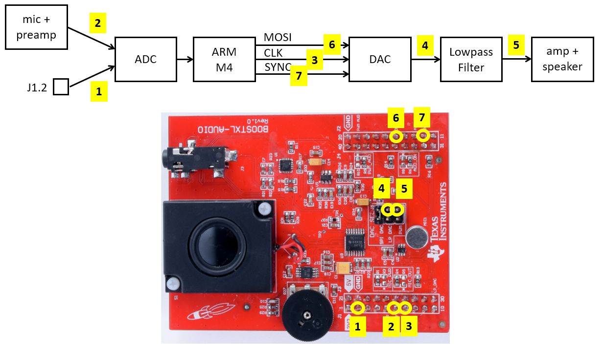
The figure below shows the signal flow block diagram of the hardware along with various measurement points on the BOOSTXL-AUDIO board where these signals can be picked up. You may find additional measurement points of interest by studying the schematics of the Data Sheets and User Guides for the MSP432 board and for the audio board.
Important
Question 2:
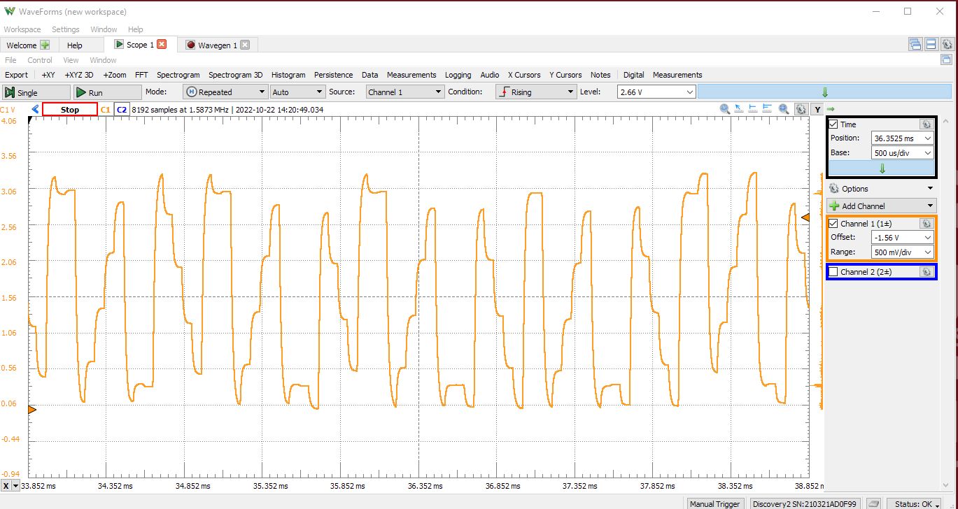
Using the oscilloscope, determine the following parameters of the audio signal created by the program
lab1_sawtooth. Determine the shape, amplitude (in V), offset (in V), and period (in s) of the signal present at point 5 in the signal flow block diagram.Make a table that describes how the numerical values computed in the
main.cof thelab1_sawtoothapplication map to the physical waveform that you see on the scope. That is, determine the lowest and highest value of the argument ofxlaudio_f32_to_dac14, and map that to voltage measurements. In addition, find the voltage level that corresponds to a floating point value of 0.0 in the program.Demonstrate that the sample rate set in the application software (
FS_16000_HZ) is consistent with the period of the waveform you observe on the oscilloscope. For example, using the C program, determine how many points are used to create the waveform, and use the sample rate to derive the waveform period you expect to observe. Then confirm that the measured waveform period matches your calculations.
Using a Waveform Generator
Next, we will study the A/D and D/A conversion range in more detail. Make a small change to the loopback program as follows. Note that the body of processSample was changed into a passthrough function, and that a parameter of the function `` xlaudio_init_intr`` is now set to XLAUDIO_J1_2_IN.
uint16_t processSample(uint16_t x) {
    float32_t v = xlaudio_adc14_to_f32(x);
    return xlaudio_f32_to_dac14(2.0 * v);
}

int main(void) {
    WDT_A_hold(WDT_A_BASE);

    xlaudio_init_intr(FS_16000_HZ, XLAUDIO_J1_2_IN, processSample);
    xlaudio_run();

    return 1;
}
Take a signal generator and configure it to create a sine-shape signal with frequency of 1 KHz, amplitude of 1V and offset 1.65V. In other words, the test signal will vary sinusoidally from 0.65V to 2.65V.
Connect this input signal on input pin J1.2 for the BOOSTXL connector (connection point 1 in the Signal Flow Diagram). Run the program and capture the output value (point 5 of the Signal Flow Diagram) on an oscilloscope. You will find that the output signal appears distored.
Reduce the signal amplitude until the point where the distortion disappears. Make a note of the amplitude when the distortion appears.
Note
Use the waveform generation capability on the Analog Discovery 2.
Important
Question 3:
With the setup of the sinus generator as described above, determine at what input amplitude a sinus function will appear undistorted at the output. Keep in mind that the offset of the input signal must be kept at 1.65V, which acts as the reference level for this A/D. Give a possible explanation for the cause of distortions when the input amplitude is bigger than the level you found.
For an undistorted output sine signal (as derived under (a)), gradually increase the frequency of the sinusoid from 1KHz to 15KHz. Describe what happens. Can you distinguish the output waveform for a 1KHz input sinusoid from the output waveform for a 15KHz sinusoid? Explain the phenomenon.
Voice recording and playback
Finally, switch to the third application in this lab, lab1_voicerecorder. This is a small audio recording example that demonstrates various features of your board. When pressing the left button of the MSP432 Launchpad, the application will record a single second of sound through the microphone. When pressing the right button of the MSP432 Launchpad, the application will play back the sound. There are three different playback modes, and every time you press the right button, the playback mode cycles to the next mode. The first mode is playback at normal speed. The second mode is playback at double speed. The third mode is playback of the time-reversed sample sequence.
Compile the program and play around with it. May sure that you understand the various constructions used in the C program.
Important
Question 4: Change the voice recording and playback program by modifying the playback modes as follows.
Change the program so that the recording mode no longer overwrites the buffer, but adds the newly recorded sound with the previously stored one. During this recording process, the signal amplitude will be reduced to to 0.75 times the original strength, so that a signal will gradually disappear during subsequent recordings.
Change the second playback mode so that it plays back the stored sound at half speed instead of double speed.
In your report, briefly describe the modifications you made to the program to achieve the described effects. Also make sure to push source code modifications back to your main repository.
Wrapping Up
The answer to this lab consists of a written report which will be added to your GitHub repository. Refer to the Report Guidelines for details on report formatting.
Not everybody in the class may be using the same setup to make oscilloscope measurements. Start your report with a short introduction on your measurement setup including the MSP-EXP432P401R kit, the oscilloscope and the signal generator that you have used for this lab.
Follow the four questions outlined above to structure your report. Use figures, screenshots and code examples where appropriate. Please work out the answers in sufficient detail to show your analysis. For example, Question 3 asks about the distortion in the signal as it leaves the DAC. To answer that question, you have to describe what you see (the observable aspects), but you also have to analyze the cause of what you see (the analytical aspects).
Make sure that you add newly developed projects to GitHub: Use the Team - Share pop-up menu and select your repository for this lab. Further, make sure that you commit and push all changes to the github repository on GitHub classroom. Use the Team - Commit pop-up menu and push all changes.
Add your final report to your GitHub repository, and push it together with the rest of the source code.
Be aware that each of the laboratory assignments in ECE4703 will require a significant investment in time and preparation if you expect to have a working system by the assignment’s due date. This course is run in “open lab” mode where it is not expected that you will be able to complete the laboratory in the scheduled official lab time. It is in your best interest to plan ahead so that you can use the TA and instructor’s office hours most efficiently.
Good Luck
Grading Rubric
Requirement |
Points |
|---|---|
Question 1 Analysis |
10 |
Question 2 Analysis |
20 |
Question 3 Analysis |
20 |
Question 4 Code and Analysis |
15 |
All projects build without errors or warnings |
10 |
Git Repository is complete and up to date |
10 |
Overall Report Quality (Format, Outline, Grammar) |
15 |
TOTAL |
100 |