L8: DMA and the ARM CMSIS Library
The purpose of this lecture is as follows.
To discuss the purpose and use of DSP libraries, with an example
To describe how DMA I/O is implemented in our DSP applications
Important
The code example for this lecture is available online as part of the Lecture 7 example repository.
DSP Libraries: ARM CMSIS
Despite the need for optimize DSP code to achieve real-time performance, there is also a relentless pressure to develop code faster. A solution for this conundrum is to make use of a library with optimized primitives. The ARM CMSIS Library contains a suite of common signal processing functions for use on Cortex-M and Cortex-A processor based devices. The advantage of such a library is threefold. First, a library improves the speed of software development. Second, the library functions can be highly optimized for the underlying architecture. Third, the library’s application programmer’s interface (API) offers a portable design that enables the same application code to execute across multiple platforms.
We’ll look at the design of a FIR filter using ARM CMSIS. In contrast to our previous design, this filter reads in a block of samples, rather than a single sample at a time. The reason for doing so is to improve the parallellism of the specification. In a typical 64-bit architecture, 16-bit samples can
be represented in parallel as a vector. Furthermore, advanced members of the ARM family have vector
instructions, which are able to perform four concurrent 16-bit operations in a 64-bit datapath.
While it’s beyond the scope of this lecture to dive into the internal details of arm_fir_q15,
you can do so on your own as the source code is available as part of the SimpleLink MSP432
package you are using on the course (See arm_fir_q15.c).
Important
void arm_fir_q15 ( const arm_fir_instance_q15 *  S,
                   const q15_t *   pSrc,
                   q15_t *   pDst,
                   uint32_t  blockSize
                 )
Parameters
[in]
Spoints to an instance of the Q15 FIR filter structure[in]
pSrcpoints to the block of input data[out]
pDstpoints to the block of output data[in]
blockSizenumber of samples to process
Returns
none
Scaling and Overflow Behavior
The function is implemented using a 64-bit internal accumulator. Both coefficients and state variables are represented in 1.15 format and multiplications yield a 2.30 result. The 2.30 intermediate results are accumulated in a 64-bit accumulator in 34.30 format. There is no risk of internal overflow with this approach and the full precision of intermediate multiplications is preserved. After all additions have been performed, the accumulator is truncated to 34.15 format by discarding low 15 bits. Lastly, the accumulator is saturated to yield a result in 1.15 format.
To use of a block-driven format, we will switch from an interrupt-driven design to a DMA-controlled design; we will discuss the details of the DMA-controlled design later.
The following application illustrates the use of arm_fir_q15.
#define NUMTAPS 32
int16_t taps[NUMTAPS + BUFLEN_SZ - 1];
int coefficients[NUMTAPS] = { (int) (1 * (1 << 15)) };
arm_fir_instance_q15 F;

initfir(arm_fir_instance_q15 *F) {
    F->numTaps  = NUMTAPS;
    F->pState   = taps;
    F->pCoeffs  = coefficients;
}

void processBuffer(uint16_t x[BUFLEN_SZ], uint16_t y[BUFLEN_SZ]) {
    adc14_to_q15_vec(x, x, BUFLEN_SZ);
    arm_fir_q15(&F, x, y, BUFLEN_SZ);
    q15_to_dac14_vec(y,y, BUFLEN_SZ);
}


#include <stdio.h>

int main(void) {
    WDT_A_hold(WDT_A_BASE);

    initfir(&F);

    msp432_boostxl_init_dma(FS_32000_HZ, BOOSTXL_J1_2_IN, BUFLEN, processBuffer);

    uint32_t c = measurePerfBuffer(processBuffer);
    printf("Cycles: %d\n", c);

    msp432_boostxl_run();

    return 1;
}
The size of the buffer with filter state is now the number of taps plus the block length minus 1 (
NUMTAPS + BUFLEN_SZ - 1). The reason for this larger buffer, is that the filter state will be updated withBUFLEN_SZsamples at a time.The filter state is stored in a record of type
arm_fir_instance_q15, which also holds the coefficients and their count. A separate initialization functioninitfiris added to initialize thearm_fir_instance_q15. Detailed documentation on arm_fir_instance_q15 can be found online.The
processSampleis now replaced with aprocessBufferfunction, which filters a block of samples. Note that MSP432_BOOSTXL_LIB has functions to convert a vector of samples from the ADC/to the DAC to internal q15, f32 or q31 datatype.The
mainfunction creates a DMA block-based setup rather than an interrupt-driven sample-based setup. The key parameter isBUFLEN, which describes the blocksize used by the DMA. We will discuss the detailed internal operation of the DMA mechanism in our next lecture. For now, the key point is that the DMA mechanism will collect a block ofBUFLENsamples (each one sample period apart) from the ADC, and then callsprocessBuffer. After this function returns, the resultingBUFLENoutput samples are submitted to the DAC, one at a time and spaced one sample period apart.
Finally, let’s look at the resulting performance of the design when using the DMA mechanism. Not surprisingly, because of the use of a DSP library, the impact of the compiler optimization is negligible. The use of a DSP library is about 2.2x faster than non-optimized code, but on the other hand, our manual optimizations outperform the DSP library filter by a factor of 2.7x. Note that this comparison is for the specific case of a Cortex-M4; and using a more powerful ARM (Cortex-A) may yield a different comparison.
processBuffer |
Non-optimized |
Optimized (size) |
Optimized (Performance) |
|---|---|---|---|
Cycle Count (Buffer) |
6088 |
6081 |
6081 |
Cycle Count (Sample) |
762 |
760 |
760 |
DMA-driven Input/Output
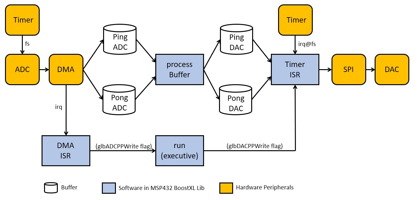
The figure above explains how the DMA mechanism works. As a block-based processing system, a conversion from sample-rate based processing to block-based, and vice versa, is needed. Two timers - one near the ADC, and one near the DAC, make sure that samples will be acquired and generated at the rate of the sample period.
The ADC completion flag triggers the DMA module, which will copy it one one of two buffers - a PING buffer or a PONG buffer. The DMA module has support at the hardware level to alternate beween these to storage buffers. The copying process from ADC output to either of these buffers is called a ‘DMA Channel’, and both of these channels are configured when you initialize the MSP432-BOOSTXL library:
// code from initADC() in msp432_boostxl_init.c

DMA_setChannelControl(DMA_CH7_ADC14 | UDMA_PRI_SELECT,
                      (UDMA_SIZE_16 | UDMA_SRC_INC_NONE | UDMA_DST_INC_16 | UDMA_ARB_1));
DMA_setChannelTransfer(DMA_CH7_ADC14 | UDMA_PRI_SELECT,
                      UDMA_MODE_PINGPONG,
                      (void*) &ADC14->MEM[0],
                      (void *) (glbPingADC),
                      glbBUFLEN);

DMA_setChannelControl(DMA_CH7_ADC14 | UDMA_ALT_SELECT,
                      (UDMA_SIZE_16 | UDMA_SRC_INC_NONE | UDMA_DST_INC_16 | UDMA_ARB_1));
DMA_setChannelTransfer(DMA_CH7_ADC14 | UDMA_ALT_SELECT,
                       UDMA_MODE_PINGPONG,
                       (void*) &ADC14->MEM[0],
                       (void *) (glbPongADC),
                       glbBUFLEN);
The DMA channel will copy glbBUFLEN samples from the ADC before a DMA completion interrupt is issued. Inside of the DMA ISR, the DMA channel is re-initialized for the next transfer, and a global flag is set for the signal processing function to start working on the newly acquired buffer.
void DMA_INT1_IRQHandler(void) {
    if(DMA_getChannelAttribute(7) & UDMA_ATTR_ALTSELECT) {
        DMA_setChannelControl(DMA_CH7_ADC14 | UDMA_PRI_SELECT,
                              (UDMA_SIZE_16 | UDMA_SRC_INC_NONE | UDMA_DST_INC_16 | UDMA_ARB_1));
        DMA_setChannelTransfer(DMA_CH7_ADC14 | UDMA_PRI_SELECT,
                               UDMA_MODE_PINGPONG,
                               (void*) &ADC14->MEM[   0],
                               (void *) (glbPingADC),
                               glbBUFLEN);
        glbADCPPWrite = PING;
    } else {
        DMA_setChannelControl(DMA_CH7_ADC14 | UDMA_ALT_SELECT,
                              (UDMA_SIZE_16 | UDMA_SRC_INC_NONE |    UDMA_DST_INC_16 | UDMA_ARB_1));
        DMA_setChannelTransfer(DMA_CH7_ADC14 | UDMA_ALT_SELECT,
                               UDMA_MODE_PINGPONG,
                               (void*) &ADC14->MEM[   0],
                               (void *) (glbPongADC),
                               glbBUFLEN);
        glbADCPPWrite = PONG;
    }
}
The processBuffer will convert a PingADC buffer of input samples into a PingDAC buffer of output samples, or else a PongADC buffer of input samples into a PongDAC buffer of output samples.
The glbBufferCallback function maps to the processBuffer function you write in your
main program.
glbADCPPRead = PING;

while (1) {

    if ((glbADCPPWrite == PING) & (glbADCPPRead == PONG)) {

        glbBufferCallback(glbPingADC, glbPingDAC);
        glbADCPPRead = PING;  // ADC PING BUFFER HAS BEEN READ
        glbDACPPWrite = PING; // DAC PING BUFFER HAS FILLED UP

    } else if ((glbADCPPWrite == PONG) & (glbADCPPRead == PING)) {

        glbBufferCallback(glbPongADC, glbPongDAC);
        glbADCPPRead = PONG;   // ADC PONG BUFFER HAS BEEN READ
        glbDACPPWrite = PONG;  // DAC PONG BUFFER HAS FILLED UP

    }

}
To run the output stream, a second timer regenerates the samples from the PingDAC buffer or else the PingDAC buffer. Notice that the dutypin signal is raised or lowered depending on what buffer is being read out. This enables you to monitor the ping-pong process. Timing issues (when the processor becomes overloaded) can be monitored when the duty cycle period is not in line with the expected timing, i.e. duty cycle period = (2 * buffer length * sample period).
DAC8311_updateDacOut(glbActiveDACBuf[glbDACBufIndex++]);

if (glbDACBufIndex == glbBUFLEN) {
    glbDACBufIndex = 0;
    if (glbDACPPWrite == PING) {
        dutypinhigh();
       glbActiveDACBuf = glbPingDAC;
    } else {
        dutypinlow();
      glbActiveDACBuf = glbPongDAC;
    }
}
Conclusions
We briefly discussed the ARM-CMSIS library, a library with pre-made DSP functions available for ARM. Lab 5 requires the use of this library, to build a biquad filter. The filter functions in ARM CMSIS use block-based processint, which requires the use of DMA-based I/O rather than interrupt driven I/O.
We briefly discussed the design of the DMA-based I/O mechanism in the MSP432-BOOSTXL library.
The code examples for this lecture are available online.