Lab 1
The purpose of this assignment is as follows.
to familiarize you with the basic MSPEXP432P401R hardware with the Audio kit,
to familiarize you with the process of editing, compiling, and downloading software with Code Composer Studio,
to familiarize you with the process of debugging software and measuring audio signals,
to verify basic notions of signal sampling and reconstruction.
Self-Study: Hardware Setup
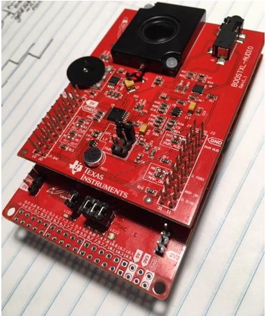
The MSPEXP432P401R is a development kit for an MSP432P401R microcontroller. The microcontroller chip includes a 48MHz ARM Cortex M4 processor with floating point arithmetic unit, 64KB of SRAM (for variables) and 256KB of Flash memory (for code). The MSP432P401R includes a collection of hardware peripherals including a 14-bit Analog to Digital converter, among others. The board contains three chips, but only one of them, the DUT, will be used to run DSP programs. Two other microcontrollers are used to program the DUT, and the measure its energy consumption. The board also has two rows of expansion headers that can be used to fit additional boards.

The audio interface for this board is implemented on a BOOSTXL-AUDIO board. This board includes a 14-bit Digital to Analog converter, audio amplifier and speaker, microphone with pre-amplifier. The board also has a jack for a headset, which will override the microphone and audio speaker with the headset audio.

The expansion headers of the BOOSTXL-AUDIO board are compatible with the headers on the MSPEXP432P401R, and both boards can be connected together to yield the hardware configuration used for real-time DSP experiments. This combo takes one single connection through your computer using the micro-USB plug on the MSPEXP432P401R board. This provides power to both boards. To learn more about this setup, consult the MSPEXP432P401R User Guide and the BOOSTXL-AUDIO User Guide. These guides are useful to consult the connection details of the expansion headers, as well as the schematics of both boards.
Self-Study: Software Setup
To complete this assignment, you will need to install the following software tools on your laptop.
You will also need to sign up for a GitHub account, in case you do not have one. All assignments in this course will be distributed as repositories and returned as updates on those repositories. If you have never worked with version control and repositories before, take some time to learn about the basics of git repositories. The GitHub Guides contain several short tutorials in checking out, committing and pushing repositories. Code Composer Studio has built-in support for git repositories.
Note
The general sequence of solving an assignment will take the following practical steps.
You will navigate to a GitHub Classroom link which will create a personal repository for the assignment. Each assignment will have its own repository. This repository is private between you and the instructor and TA, meaning that only you, the instructor and the TA will have access to it.
You will download the assignment repository into CCS. The assignments typically will come with some starter code that you need to further complete while solving the assignment. Using CCS, you can develop code, compile code, download binary programs to the hardware kit, and debug programs running on the hardware kit.
When you have solved the assignment, you will upload the modifications that you made to the repository to GitHub. This can be done from within CCS. GitHub records the time of the uploads. The assignment turn-in time will be the most recent update to your assignment repository. The turn-in time is important as it determines if you have completed the assignment late.
Downloading the Assignment code in CCS
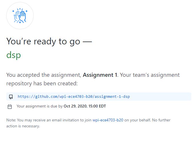
This assignment can be solved in teams of up to three people. Discuss among yourselves to form a team. When ready, navigate to GitHub classroom by clicking on the following link: https://classroom.github.com/g/rLOQExDq. The link will ask you to either join an existing team or else form a new team. Your repository will then be created. The repository link will have your team name. For example, if your team is named dsp, you will find that the following repository is created.
Downloading the assignment repository
Copy the repository link, https://github.com/wpi-ece4703-b20/assignment-1-dsp to the clipboard and start code composer studio. Take the following steps to download the repository into CCS.
In the project explorer pane, right-click and select Import .. from the pulldown menu, followed by Import.
A source selection window opens. Select Git and Projects from Git.
A repository selection window opens. Select Clone URI.
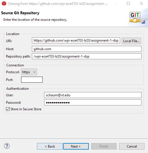
Enter the Team repository URI, as well as your GitHub credentials, in the next Source Git Repository window.
Select the master branch, and choose an appropriate local destination for your repository. The local destination must be a directory on your local harddrive. The default selection of CCS is R:/git/repositoryname - which is most likely not a drive letter that you have available. Click Browse and find a good destination. That would typically be C:/username/git.
Select all projects available from the Assignment Repository. That includes two projects: a1_blinking_led and a1_polled_loopback.
Downloading the support library
All projects also make use of a support library specifically developed for this class. The support library will be shared among all assignments and has to be downloaded only once. It is available in a repository by itself: https://github.com/wpi-ece4703-b20/msp432_boostxl_lib. Download this library into CCS in the same manner as you did for your assignment code.
In the project explorer pane, right-click and select Import .. from the pulldown menu, followed by Import.
A source selection window opens. Select Git and Projects from Git.
A repository selection window opens. Select Clone URI.
Enter the support library URI, as well as your GitHub credentials, in the next Source Git Repository window.
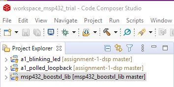
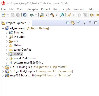
When the download completes, the CCS project explorer will now contain three projects as shown below. Two of these projects are part of Assignment 1. The third is a support library.
Running the first program: blinking LED
You are now ready to run the first example, a1_blinking_led. This code blinks red LED on the main board. Study the code and analyze how it works.
The function msp432_boostxl_init() is used to initialize the support library. It ensures that the ARM Cortex M4 will run at 48MHz. The errorledon() and errorledoff() functions are provided in the support library. Note how time is measured in this design, by counting clock cycles. Between each LED toggle, an artifical delay of 10,000,000 clock cycles is inserted.
 1#include <ti/devices/msp432p4xx/driverlib/driverlib.h>
 2#include "msp432_boostxl_init.h"
 3
 4int main(void) {
 5    WDT_A_hold(WDT_A_BASE);
 6
 7    msp432_boostxl_init();
 8
 9    while (1) {
10        errorledon();
11        __delay_cycles(10000000);
12        errorledoff();
13        __delay_cycles(10000000);
14    }
15
16    return 1;
17}
To compile this program, you have to build the support library, as well as the application a1_blinking_led. To compile in CCS, right-click the library and select ‘build project’. Do the same for a1_blinking_led. When a program compiles, the Build Console in CCS displays diagnostic information such as warnings and errors. The diagnostic information is important. Verify the diagnostics and use this as a method to avoid errors in your software.
Once the program successfully compiles, you can download it on the board and run it. The quickest to achieve this is to run the debugger, available by clicking the small bug in the top menu of CCS. As the debugger initializes, it will download the program to the board and halt execution just at the start of the main function. You can continue execution by pressing the green play button. The LED on the MSP432 board will now blink. To exit the debugger, press the stop button. This will return you to the edit window. Once you exit the debugger, the program loaded onto the hardware continues to execute. In this case, the LED continues to blink.
Before moving on, take a moment to make sure you understand all the steps involved in editing, compiling, and running a program.
Try to change the behavior of the blinking LED. For example, build a blinking LED that blinks three times per second with a 25% duty cycle. After you have made modifications to the application, build it in the compiler, and run it on the MSP432 board.
Exit CCS, power off the board. Start CCS again and power up the board again. Go through the steps of reprogramming the blinking LED application.
In the debugger, set a a breakpoint at
errorledoff(). Single-step through the code (yellow arrow right besides the red stop button). Describe the implementation of theerrorledoff()function. Single-step further intoGPIO_setAsOutputPin( GPIO_PORT_P1, GPIO_PIN0). The source code for this function, which is part of the MSP432 low-level library, is not known to the debugger. Find how the debugger deals with this. Finally remove the breakpoint and press the continue button.
1void errorledoff() {
2    GPIO_setAsOutputPin( GPIO_PORT_P1, GPIO_PIN0);
3    GPIO_setOutputLowOnPin( GPIO_PORT_P1, GPIO_PIN0);
4}
The loopback application
You are now ready to work on the loopback application. Study the program as you did for the LED.
 1#include <ti/devices/msp432p4xx/driverlib/driverlib.h>
 2#include "msp432_boostxl_init.h"
 3
 4uint16_t processSample(uint16_t in) {
 5    return in;
 6}
 7
 8int main(void) {
 9    WDT_A_hold(WDT_A_BASE);
10
11    msp432_boostxl_init_poll(BOOSTXL_MIC_IN,
12                             processSample);
13
14    msp432_boostxl_run();
15
16    return 1;
17}
This program does a loopback function. It repeatedly reads a sample from the microphone, sends the value of the sample to processSample and returns the resulting ouptut to the audio amplifier.
The function `` msp432_boostxl_init_poll(BOOSTXL_MIC_IN, processSample)`` sets up a callback function. Each time the analog-to-digital converter delivers a sample, it will pass on the value of that sample to processSample. The output of processSample will be delivered to the digital-to-analog converter, which eventually plays the sample on the speaker. Then the process starts over, and the next audio sample is converted from the microphone. This process happens as fast as possible, and is called a polling-mode input-output mechanism. As fast as possible does not mean ‘infinitely fast’. Making A/D conversions and sendind samples to the D/A converter takes time. In addition, the processor runs at 48MHz - quite fast, but not infinite. All these factors combined limit the speed at which samples are moved from the microphone to the speaker.
Important
Question 1: Run the loopback application on the board. What do you hear? Explain what is happening.
Connecting the Oscilloscope
For the next experiment, you need to an oscilloscope - either one from a lab bench setup, or else a USB scope connected to your laptop. The examples on this page are made using an Analog Discovery USB Scope from Digilent - but other models are equally fine. Refer to the usb_scope section in the Technical Documentation pages.
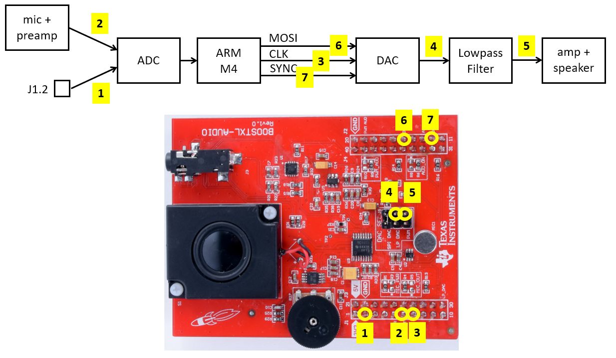
The figure below shows the signal flow block diagram of the hardware along with various measurement points on the AUDIO XL board where these signals can be picked up. You may find additional measurement points of interest by studying the schematics of the MSP-EXP432P401R Kit as well as the audio board.
Important
Question 2: Use an oscilloscope to determine the DAC sample rate of the polling input/output program. Explain how you came to that conclusion.
To determine the A/D and D/A conversion range, we will make a small change to the loopback program. Instead of reading input from the microphone, you will change the program to read input from pin J1.2.
Change the function call to msp432_boostxl_init_poll as follows:
msp432_boostxl_init_poll(BOOSTXL_J1_2_IN,
                         processSample);
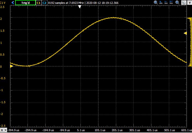
Take a signal generator and configure it to create a sine-shape signal with frequency of 1 KHz, amplitude of 1V and offset 1V. In other words, the input signal on pin J1.2 will vary sinusoidally from 0V to 2V. Run the program and capture the output on an oscilloscope.
Does the signal appear undistorted?
Important
Question 3: Use an oscilloscope to capture the output to the audio amplifier. Does the signal appear undistorted? Hint: measure the signal both before and after the lowpass filter at the output of the DAC. Explain what you see. In particular, explain the distortions that appear on the sine wave.
Determining the range and resolution of A/D and D/A
Your next task is to determine the span and voltage resolution of the A/D and D/A conversion. Based on the technical specification, the resolution of the A/D and D/A are identical, and equal to 14 bit. The A/D and D/A codes are unsigned numbers with values from 0 (smallest code) to 2^14 - 1 = 16,383 (largest code). From the previous experiment, we also found that the analog range of voltages on the A/D side maps to the same range of voltages on the D/A side.
Important
Question 4: Make changes to the loopback program so that you can test what D/A voltage corresponds to the lowest and largest code. Given these two analog values, determine the span of the D/A. Show your program and explain how it works.
Real-time signal processing
You will now develop a new application which will compute and return the sum over the last five input samples. Instead of polling, you will use a give sample rate of 24KHz. Refer to the documentation for the MSP432_BOOSTXL_LIB library, and specifically to the function msp432_boostxl_init_intr.
You can refer to the loopback example on how to set up your application. Create the application as a new project in Code Composer Studio. The name of the new application should be a1_average. The easiestway to create this application is to copy the loopback example and to rename that example; all these operations are supported directly in the GUI. Here is how the GUI should look like if you have copied the project.
Important
Question 5: Write the averaging application according to the parameters specified above (24 KHz sample rate, 5-tap sum). Configure the application to read from input J1.2. At the input, apply a 2KHz square wave. The square wave has a 100mV amplitude and a 100mV offset, i.e. it switches up and down between 0V and 200mV. Use the scope to capture the output waveform. Explain the shape of the output waveform in function of the sample rate of the application, and the application that is running.
Wrapping Up
The answer to this lab consists of a written report which will be emailed to the instructor and the TA by the deadline. Refer to the General Lab Report Guidelines for details on report formatting. You will only submit your written report by email. All code developed must be returned through github.
Not everybody in the class may be using the same setup to make oscilloscope measurements. Start your report with a short introduction on your measurement setup including the MSP-EXP432P401R kit, the oscilloscope and the signal generator that you have used for this lab.
Follow the five questions outlined above to structure your report. Use figures, screenshots and code examples where appropriate. Please work out the answers in sufficient detail to show your analysis. For example, Question 3 asks about the distortion in the signal as it leaves the DAC. To answer that question, you have to describe what you see (the observable aspects), but you also have to analyze the cause of what you see (the analytical aspects).
Make sure that you add newly developed projects to github: Use the Team - Share pop-up menu and select your repository for this lab, such as https://github.com/wpi-ece4703-b20/assignment-1-dsp). Further, make sure that you commit and push all changes to the github repository on GitHub classroom. Use the Team - Commit pop-up menu and push all changes.
Be aware that each of the laboratory assignments in ECE4703 will require a significant investment in time and preparation if you expect to have a working system by the assignment’s due date. This course is run in “open lab” mode where it is not expected that you will be able to complete the laboratory in the scheduled official lab time. It is in your best interest to plan ahead so that you can use the TA and instructor’s office hours most efficiently.
Good Luck
Grading Rubric
Requirement |
Points |
|---|---|
Question 1 Analysis |
15 |
Question 2 Analysis |
15 |
Question 3 Analysis |
15 |
Question 4 Analysis |
15 |
Question 5 Analysis |
15 |
All projects build without errors or warnings |
5 |
Code is well structured and commented |
5 |
Git Repository is complete and up to date |
5 |
Overall Report Quality (Format, Outline, Grammar) |
10 |
TOTAL |
100 |